Siemens SIMATIC NET RUGGEDCOM RX1536 Installation Manual
Rugged multi service platforms
Hide thumbs
Also See for SIMATIC NET RUGGEDCOM RX1536:
- Equipment manual (56 pages) ,
- Reference manual (252 pages)

Related Manuals for Siemens SIMATIC NET RUGGEDCOM RX1536


Summary of Contents for Siemens SIMATIC NET RUGGEDCOM RX1536
- Page 1 Installation Manual SIMATIC NET Rugged Multi Service Platforms RUGGEDCOM RX1536 Edition 04/2021 https://www.siemens.com...
- Page 2 Preface Introduction Installing the Device SIMATIC NET Device Management Rugged Multi Service Platforms RUGGEDCOM RX1536 Modules Technical Specifications Installation Manual Certification 04/2021 C79000-G8976-1488-02...
- Page 3 Note the following: WARNING Siemens products may only be used for the applications described in the catalog and in the relevant technical documentation. If products and components from other manufacturers are used, these must be recommended or approved by Siemens. Proper transport, storage, installation, assembly, commissioning, operation and maintenance are required to ensure that the products operate safely and without any problems.
-
Page 4: Table Of Contents
Accessing Documentation ....................... v Registered Trademarks ......................v Warranty ..........................vi Training ..........................vi Customer Support ........................vi Contacting Siemens ....................... vii Introduction ........................... 1 Feature Highlights ....................1 Description ......................1 Required Tools and Materials ................. 2 Decommissioning and Disposal ................3 Cabling Recommendations .................. - Page 5 Table of Contents Technical Specifications ...................... 43 Power Supply Specifications ................43 Failsafe Relay Specifications ................43 Operating Environment ..................44 Mechanical Specifications ..................44 Dimension Drawings ................... 44 Certification ......................... 49 Approvals ......................49 6.1.1 UL ........................49 6.1.2 TÜV SÜD ......................
-
Page 6: Preface
Siemens Customer Support. Registered Trademarks RUGGEDCOM®, ROS®, RCDP®, and RUGGEDCOM Discovery Protocol® are registered trademarks of Siemens Canada Ltd. Linux® is the registered trademark of Linus Torvalds in the United States and other countries. The registered trademark Linux® is used pursuant to a sublicense from LMI, the exclusive licensee of Linus Torvalds, owner of the mark on a world-wide basis. -
Page 7: Warranty
Preface Warranty Warranty Siemens warrants this product for a period of five (5) years from the date of purchase, conditional upon the return to factory for maintenance during the warranty term. This product contains no user-serviceable parts. Attempted service by unauthorized personnel shall render all warranties null and void. -
Page 8: Contacting Siemens
Call a local hotline center to submit a Support Request (SR). To locate a local hotline center, visit https://w3.siemens.com/aspa_app/?lang=en. Mobile App Install the Industry Online Support app by Siemens AG on any Android, Apple iOS or Windows mobile device and be able to: •... - Page 9 Preface Contacting Siemens viii RUGGEDCOM RX1536 Installation Manual, 04/2021, C79000-G8976-1488-02...
-
Page 10: Introduction
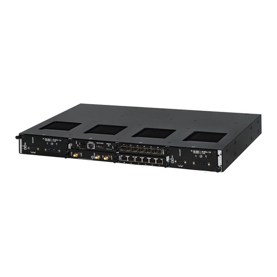
Introduction The RUGGEDCOM RX1536 is a cost-efficient, rugged Layer 3 switch and router. The RUGGEDCOM RX1536’s modular and field replaceable platform can be equipped with WAN, serial, and Ethernet options, making it ideally suited for electric power utilities, the industrial plant floor, and traffic control systems. The RUGGEDCOM RX1536 is designed to provide a high level of immunity to electromagnetic interference (EMI) and heavy electrical surges typical of the harsh environments found in many industrial applications. -
Page 11: Required Tools And Materials
Introduction 1.3 Required Tools and Materials Management Port RS232 Serial Console Port (DB9) Utility USB Port Port Status LEDs Power Status LEDs Alarm Indicator LED Lamp Test/Alarm Cut-Off (LT/ACO) Button Figure 1.1 RUGGEDCOM RX1536 Management Port This 10/100Base-T Ethernet port is used for system management that is out-of-band from the switch fabric. -
Page 12: Decommissioning And Disposal
Recycling and disposal must be done in accordance with local regulations. Cabling Recommendations Siemens recommends using SIMATIC NET industrial Ethernet shielded cables for all Ethernet ports. 1.5.1 Protection On Twisted-Pair Data Ports... -
Page 13: Gigabit Ethernet 1000Base-Tx Cabling Recommendations
Siemens also does not recommend using copper Ethernet ports to interface with devices in the field across distances that could produce high levels of ground potential rise (i.e. greater than 2500 V), during line-to-ground fault conditions. -
Page 14: Installing The Device
Installing the Device This chapter describes how to install the device, including mounting the device, connecting power, and connecting the device to the network. DANGER Electrocution hazard – risk of serious personal injury and/or damage to equipment. Before performing any maintenance tasks, make sure all power to the device has been disconnected and wait approximately two minutes for any remaining energy to dissipate. -
Page 15: General Procedure
This product contains no user-serviceable parts. Attempted service by unauthorized personnel shall render all warranties null and void. Changes or modifications not expressly approved by Siemens AG could invalidate specifications, test results, and agency approvals, and void the user's authority to operate the equipment. -
Page 16: Mounting The Device
2.3 Mounting the Device Verify all items are included. Note If any item is missing or damaged, contact Siemens for assistance. Mounting the Device The RUGGEDCOM RX1536 is designed for maximum mounting and display flexibility. It can be equipped with connectors that allow it to be installed in a 48 cm (19 in) rack, 35 mm (1.4 in) DIN rail or directly on a panel. -
Page 17: Mounting The Device On A Din Rail
Installing the Device 2.3.2 Mounting the Device on a DIN Rail • Do not exceed the maximum number of devices or weight restrictions specified by the rack manufacturer. • Do not overload the supply circuit. Refer to the over-current protection and power supply ratings specified by the rack manufacturer. -
Page 18: Mounting The Device To A Panel
Installing the Device 2.3.3 Mounting the Device to a Panel To mount the device to a DIN rail, do the following: Align the adapters with the DIN rails and slide the device into place. Panel/DIN Rail Adapter DIN Rail Screw Figure 2.2 DIN Rail Mounting Install one of the supplied screws on either side of the device to secure the adapters to the DIN rails. -
Page 19: Connecting The Failsafe Alarm Relay
Installing the Device 2.4 Connecting the Failsafe Alarm Relay To mount the device to a panel, do the following: Place the device against the panel and mark the mounting holes on the panel. Screw Panel/DIN Rail Adapter Figure 2.3 Panel Mounting Prepare the mounting holes Align the device with the mounting holes and secure it to the panel. -
Page 20: Connecting Power
Installing the Device 2.5 Connecting Power Normally Open Common Normally Closed Figure 2.4 Failsafe Alarm Relay Wiring Connecting Power Power modules can be equipped with either a screw or European-style (Euroblock) terminal block. The screw terminal block is installed using Phillips screws and compression plates, allowing either bare wire connections or crimped terminal lugs. -
Page 21: Connecting High Ac/Dc Power
Installing the Device 2.5.1 Connecting High AC/DC Power 2.5.1 Connecting High AC/DC Power To connect a high AC/DC power supply to the device, do the following: DANGER Electrocution hazard – risk of death, serious personal injury and/or damage to the device Make sure the supplied cover is always installed over high voltage screw terminal blocks. - Page 22 Installing the Device 2.5.1 Connecting High AC/DC Power Connect the power supply terminal block to the device. European-style (Euroblock) Terminal Block Positive/Live (+/L) Terminal Ground Terminal Negative/Neutral (-/N) Terminal Figure 2.5 AC Terminal Block Wiring – European-style (Euroblock) Terminal Block for HIP Power Supplies Not Connected Removable Screw Terminal Block...
- Page 23 Installing the Device 2.5.1 Connecting High AC/DC Power Negative/Neutral (-/N) Terminal Figure 2.6 AC Terminal Block Wiring – Screw Terminal Block for HI Power Supplies Note For secure, reliable connections under severe shock or vibration, use M3.5 ring lugs with a maximum outer diameter of 7 mm (0.28 in). Make sure no bare metal is exposed beyond the safety cover.
-
Page 24: Connecting Low Dc Power
Installing the Device 2.5.2 Connecting Low DC Power Using a #10 ring lug and #10-32 screw, secure the ground terminal on the power source to the ground connection on the device. Make sure the lug is tightened to 1.1 N·m (9.5 lbf·in). #10 Ring Lug #10-32 Screw Connection from External Power Source... - Page 25 Installing the Device 2.5.2 Connecting Low DC Power Connect the power supply terminal block to the device. European-style (Euroblock) Terminal Block Positive (+) Terminal Negative (-) Terminal Ground Terminal Figure 2.9 DC Terminal Block Wiring – European-style (Euroblock) Terminal Block for 12P, 24P and 48P Power Supplies Not Connected Removable Screw Terminal Block...
- Page 26 Installing the Device 2.5.2 Connecting Low DC Power Ground Terminal Figure 2.10 DC Terminal Block Wiring – Screw Terminal Block for 12P, 24P and 48P Power Supplies European-style (Euroblock) Terminal Block Positive (+) Terminal Negative (-) Terminal Ground Terminal Figure 2.11 DC Terminal Block Wiring – European-style (Euroblock) Terminal Block for -12P, -24P and -48P Power Supplies Not Connected Removable Screw Terminal Block...
- Page 27 Installing the Device 2.5.2 Connecting Low DC Power Ground Terminal Figure 2.12 DC Terminal Block Wiring – Screw Terminal Block for -12P, -24P and -48P Power Supplies Note For secure, reliable connections under severe shock or vibration, use M3.5 ring lugs with a maximum outer diameter of 7 mm (0.28 in). Make sure no bare metal is exposed beyond the safety cover.
- Page 28 Installing the Device 2.5.2 Connecting Low DC Power Using a #10 ring lug and #10-32 screw, secure the ground terminal on the power source to the ground connection on the device. Make sure the lug is tightened to 2.4 N·m (21 lbf·in). #10 Ring Lug #10-32 Screw Connection from External Power Source...
- Page 29 Installing the Device 2.5.2 Connecting Low DC Power RUGGEDCOM RX1536 Installation Manual, 04/2021, C79000-G8976-1488-02...
-
Page 30: Device Management
It may cause damage to the contact pins of the RJ45 ports. For a permanent solution, use Siemens 6XV1870-3Qxxx certified cables (manufactured December 2019 or after) or equivalent. Siemens recommends using Siemens certified cables and connectors for Siemens RUGGEDCOM products. - Page 31 Device Management 3.1 Connecting to the Device Serial Console and Management Ports Connect a workstation directly to the serial console or management ports to access the boot-time control and RUGGEDCOM RX1536 interfaces. The serial console port provides access to RUGGEDCOM RX1536 's console interface, while the management port provides access to RUGGEDCOM RX1536's console and Web interfaces.
-
Page 32: Configuring The Device
Device Management 3.2 Configuring the Device Note Single-mode fiber ports only support Ultra Physical Contact (UPC) cable connectors. Configuring the Device Once the device is installed and connected to the network, it must be configured. All configuration management is done via the RUGGEDCOM RX1536 interface. For more information about configuring the device, refer to the RUGGEDCOM ROX Configuration Manual associated with the installed software release. - Page 33 Device Management 3.2 Configuring the Device RUGGEDCOM RX1536 Installation Manual, 04/2021, C79000-G8976-1488-02...
-
Page 34: Modules
Modules The RUGGEDCOM RX1536 features slots for up to six field-replaceable line modules, which can be used to expand and customize the capabilities of the device to suit specific applications. A variety of modules are available, each featuring a specific type of communication port: copper Ethernet, fiber optic Ethernet, SFP, WAN, cellular modem and DDS. -
Page 35: Available Modules
Available Modules The following is a list of all power and line modules available for use in the RUGGEDCOM RX1536. For more information about individual modules, refer to the RUGGEDCOM RX1500 Series Modules Catalog [https://support.industry.siemens.com/ cs/ca/en/view/109747072]. RUGGEDCOM RX1536 Installation Manual, 04/2021, C79000-G8976-1488-02... - Page 36 Modules 4.2 Available Modules Power Supply Modules RUGGEDCOM RX1500PN PS 12 (shipped until Specifications Article Numbers 2019) Input Range: 9 to 15 6GK6015-0AL17-0AA0 (Standard) Terminal Type: Non- 6GK6015-0AL17-0AA1 removable Screw (Conformal Coated) RUGGEDCOM RX1500PN PS 12 (shipped from Specifications Article Numbers 2019 on) Input Range: 9 to 15 6GK6015-0AL17-0AA0...
- Page 37 Modules 4.2 Available Modules RUGGEDCOM RX1500PN PS 48 (shipped until Specifications Article Numbers 2019) Input Range: 36 to 72 6GK6015-0AL12-0AA0 (Standard) Terminal Type: Non- 6GK6015-0AL12-0AA1 removable Screw (Conformal Coated) RUGGEDCOM RX1500PN PS 48 (shipped from Specifications Article Numbers 2019 on) Input Range: 36 to 72 6GK6015-0AL12-0AA0 (Standard) Terminal Type:...
- Page 38 Modules 4.2 Available Modules Input Range: 88 to 300 6GK6015-0AL16-0AA0 VDC or 85 to 264 VAC (Standard) Terminal Type: 6GK6015-0AL16-0AA1 European-style (Conformal Coated) (Euroblock) Copper Ethernet Modules RUGGEDCOM RX1500PN LM CG01 Specifications Article Numbers Ports: 2 6GK6015-0AL20-0FC0 (Standard) Speed: 1000 Mbps 6GK6015-0AL20-0FC1 Interface: TX (Conformal Coated)
- Page 39 Modules 4.2 Available Modules RUGGEDCOM RX1500PN LM X CG04B Specifications Article Numbers Ports: 2 6GK6015-0AL20-0PJ0 (Standard) Speed: 1000 Mbps 6GK6015-0AL20-0PJ1 Interface: TX (Conformal Coated) Port Type: M12 (8-pin, X-Coded, Controlled Bypass) Distance: 100 m (328 ft) Power Consumption: 4 RUGGEDCOM RX1500PN LM 4TX03 Specifications Article Numbers Ports: 4...
- Page 40 Modules 4.2 Available Modules Power Consumption: 5 RUGGEDCOM RX1500PN LM 6TX01 Specifications Article Numbers Ports: 6 6GK6015-0AL20-0NB0 (Standard) Speed: 100 Mbps 6GK6015-0AL20-0NB1 Interface: TX (Conformal Coated) Port Type: RJ45 Distance: 100 m (328 ft) Power Consumption: 5 Fiber Optic Ethernet Modules RUGGEDCOM RX1500PN LM 4FX11 Specifications Article Numbers...
- Page 41 Modules 4.2 Available Modules SFP Sockets: 2 6GK6015-0AL20-0JB0 (Standard) Speed: 1000 Mbps 6GK6015-0AL20-0JB1 Power Consumption: 7 (Conformal Coated) RUGGEDCOM RX1500PN LM FG51 Specifications Article Numbers Mode: MM GK60150-AL200-DC0 (Standard) Speed: 1000 Mbps GK60150-AL200-DC1 Interface: SX (Conformal Coated) Wavelength: 820 nm Ports: 2 Port Type: LC Distance: 500 m (1640 Power Consumption: 5...
- Page 42 Modules 4.2 Available Modules Power Consumption: 7 WAN Modules RUGGEDCOM RX1500PN LM S01 Specifications Article Numbers Standard: RS232/RS422/ 6GK6015-0AL20-0KB0 RS485 (Standard) Ports: 6 6GK6015-0AL20-0KB1 (Conformal Coated) Port Type: RJ45 Power Consumption: 3 Cellular Modem Modules RUGGEDCOM RX1500PN LM W11 Specifications Article Numbers Services: GSM/EDGE/ 6GK6015-0AL20-0WB0 HSPA+...
- Page 43 Modules 4.2 Available Modules Region: North America (AT&T, Rogers, Bell, Telus) Port Type: 50 Ω SMA Antennas: 1 x LTE Main, 1 x LTE MIMO, 1 x GPS SIM: Dual Mini-SIM (2FF) Power Consumption: 7 RUGGEDCOM RX1500PN LM W61 Specifications Article Numbers Services: 4G LTE/HSPA+/ 6GK6015-0AL20-0WJ0 CDMA/EVDO/GPS/GNSS...
- Page 44 Modules 4.2 Available Modules Networking: Realtek RTL8111, RJ45 Gigabit Ethernet Interface USB: 2 x USB 2.0 Video: Intel 4108 Graphics Processor, DVI- Power Consumption: 10 RUGGEDCOM RX1500PN LM APE1402W7 Specifications Article Numbers (Obsolete) Operating System: 6GK6015-0AL20-0GC0 Windows® Embedded (Standard) Standard 7 6GK6015-0AL20-0GC1 Processor: Intel Atom (Conformal Coated)
- Page 45 Modules 4.2 Available Modules Operating System: 6GK6015-0AL20-0GG1 Debian Linux® and (Conformal Coated) CROSSBOW ADM Processor: Intel Atom E660T 1.3 GHz, 512 KB L2 Cache RAM: 2 GB DDR2, 800 MHz, 32-bit Disk: 16 GB SATA, Solid State Networking: Realtek RTL8111, RJ45 Gigabit Ethernet Interface USB: 2 x USB 2.0 Video: Intel 4108...
- Page 46 Modules 4.2 Available Modules Networking: Realtek RTL8111, RJ45 Gigabit Ethernet Interface USB: 2 x USB 2.0 Video: Intel 4108 Graphics Processor, DVI- Power Consumption: 10 RUGGEDCOM RX1536PN LM APE1808LNX Specifications Article Numbers Operating System: 6GK6015-0AL20-0GH0 Debian Linux® (Standard) Processor: Intel x5- 6GK6015-0AL20-0GH1 E3940 1.8 GHz, 2 MB L2 (Conformal Coated)
- Page 47 Modules 4.2 Available Modules RAM: 8 GB DDR3 ECC, 1600 MHz, 64-bit Disk: 64 GB, Solid State Networking: Intel I210, RJ45 Gigabit Ethernet Interface USB: 2 x USB 3.0 Video: Intel HD Graphics Processor, Display Port Power Consumption: 12 RUGGEDCOM RX1536PN LM APE1808CKP Specifications Article Numbers Operating System:...
-
Page 48: Installing/Removing Line Modules
Modules 4.3 Installing/Removing Line Modules Installing/Removing Line Modules Upon installing a new line module in the device, all features associated with the module are available in RUGGEDCOM RX1536 . For more information, refer to the RUGGEDCOM ROX Configuration Manual for the RUGGEDCOM RX1536. Once a line module is removed, all the features associated with the module are hidden or disabled in RUGGEDCOM RX1536. - Page 49 Modules 4.3 Installing/Removing Line Modules Pull the module from the chassis to disconnect it. Module Chassis Screw Figure 4.2 Removing a Module Install a new module or a blank module (to prevent the ingress of dust and dirt). [Optional] If necessary, install the device in the rack. Installing a Module To install a line module, do the following: [Optional] If the device is installed in a rack, remove it from the rack.
-
Page 50: Installing/Removing Power Modules
Modules 4.4 Installing/Removing Power Modules Installing/Removing Power Modules Figure 4.4 NOTICE Contamination hazard – risk of equipment damage Prevent the ingress of water, dirts and other debris that may lead to premature equipment failure. Always make sure slots are not left empty. Removing a Power Module To remove a power module, do the following: DANGER... - Page 51 Modules 4.4 Installing/Removing Power Modules Disconnect the power supply wiring from the terminal block. Alternatively, for convenience, remove the terminal block with the wiring still connected and set it aside to be connected later to the new module. Install a new or blank module to prevent the ingress of dust and dirt. Installing a Power Module To install a power module, do the following: If equipped, remove the existing module.
-
Page 52: Technical Specifications
Technical Specifications This section provides important technical specifications related to the device. Power Supply Specifications Note When determining cable lengths, make sure the minimum input voltage for the power supply is provided at the power source. Input Range Maximum Power Internal Power Insulation... -
Page 53: Operating Environment
Technical Specifications 5.3 Operating Environment Operating Environment The RUGGEDCOM RX1536 is rated to operate under the following environmental conditions. Note Temperature limits for select line modules may differ from that which can be withstood by the RUGGEDCOM RX1536. Make sure the selected modules are rated for the expected environmental conditions before deployment. - Page 54 Technical Specifications 5.5 Dimension Drawings 440.9 Figure 5.1 Overall Dimensions RUGGEDCOM RX1536 Installation Manual, 04/2021, C79000-G8976-1488-02...
- Page 55 Technical Specifications 5.5 Dimension Drawings 21.1 463.8 11.7 Figure 5.2 Rack Mount Dimensions 479.0 21.1 11.7 489.2 Figure 5.3 Panel and Din Rail Mount Dimensions RUGGEDCOM RX1536 Installation Manual, 04/2021, C79000-G8976-1488-02...
- Page 56 Technical Specifications 5.5 Dimension Drawings 162.5 151.4 19.7 Figure 5.4 Line Module Dimensions 162.5 151.8 40.6 Figure 5.5 Power Module Dimensions RUGGEDCOM RX1536 Installation Manual, 04/2021, C79000-G8976-1488-02...
- Page 57 Technical Specifications 5.5 Dimension Drawings RUGGEDCOM RX1536 Installation Manual, 04/2021, C79000-G8976-1488-02...
-
Page 58: Certification
Certification The RUGGEDCOM RX1536 device has been thoroughly tested to guarantee its conformance with recognized standards and has received approval from recognized regulatory agencies. Note Certifications related to individual modules are detailed in the RUGGEDCOM Modules Catalog for the device available online. Approvals This section details the standards to which the RUGGEDCOM RX1536 complies. -
Page 59: European Union (Eu)
Certification 6.1.3 European Union (EU) 6.1.3 European Union (EU) This device is declared by Siemens AG to comply with essential requirements and other relevant provisions of the following EU directives: • Directive 2014/30/EU Directive 2014/30/EU of the European Parliament and of the Council of 26... -
Page 60: Fcc
The device is marked with a CE marking and notified body number, and can be used throughout the European community. 0680 A copy of the CE Declaration of Conformity is available from Siemens AG. For contact information, refer to "Contacting Siemens (Page vii)". -
Page 61: Iso
Quality management systems – Requirements 6.1.8 RoHS This device is declared by Siemens AG to meet the requirements of the following RoHS (Restriction of Hazardous Substances) directives for the restricted use of certain hazardous substances in electrical and electronic equipment: •... - Page 62 2 kV (Failsafe Relay output) DC Power Ports 1.5 kV AC Power Ports 2 kV HV Impulse Signal ports 5 kV (Failsafe Relay output) DC Power Ports 5 kV AC Power Ports Siemens-specified severity levels. RUGGEDCOM RX1536 Installation Manual, 04/2021, C79000-G8976-1488-02...
- Page 63 Certification 6.2 EMC and Environmental Type Tests EMC Immunity Type Tests for IEEE 1613 Note The RUGGEDCOM RX1536 meets Class 2 requirements for an all-fiber configuration and Class 1 requirements for copper ports. Class 1 allows for temporary communication loss, while Class 2 requires error-free and interrupted communications.
- Page 64 Certification 6.2 EMC and Environmental Type Tests Test Description Test Levels Severity Levels IEC 60529 Ingress Protection IP4x Military Standard Tests Test Description Test Levels MIL-STD-810G Altitude 12192 m (40000 ft) @ 40 °C, 90 minutes RUGGEDCOM RX1536 Installation Manual, 04/2021, C79000-G8976-1488-02...
- Page 65 Certification 6.2 EMC and Environmental Type Tests RUGGEDCOM RX1536 Installation Manual, 04/2021, C79000-G8976-1488-02...
- Page 66 Further Information Siemens RUGGEDCOM https://www.siemens.com/ruggedcom Industry Online Support (service and support) https://support.industry.siemens.com Industry Mall https://mall.industry.siemens.com Siemens AG Digital Industry Process Automation Postfach 48 48 90026 NÜRNBERG GERMANY...
Need help?
Do you have a question about the SIMATIC NET RUGGEDCOM RX1536 and is the answer not in the manual?
Questions and answers