Siemens SIMATIC NET SCALANCE W M766 Series Operating Instructions Manual
Industrial wireless lan
Hide thumbs
Also See for SIMATIC NET SCALANCE W M766 Series:
- Operating instructions manual (82 pages) ,
- Operating instructions manual (86 pages)
Table of Contents
Advertisement
Advertisement
Table of Contents

Related Manuals for Siemens SIMATIC NET SCALANCE W M766 Series


Summary of Contents for Siemens SIMATIC NET SCALANCE W M766 Series
- Page 1 Introduction Safety notices Security recommendations SIMATIC NET Description of the device Industrial Wireless LAN SCALANCE WxM766 Mounting Connection Operating Instructions Upkeep and maintenance Technical specifications Dimension drawing Approvals 07/2021 C79000-G8976-C617-02...
- Page 2 Note the following: WARNING Siemens products may only be used for the applications described in the catalog and in the relevant technical documentation. If products and components from other manufacturers are used, these must be recommended or approved by Siemens. Proper transport, storage, installation, assembly, commissioning, operation and maintenance are required to ensure that the products operate safely and without any problems.
-
Page 3: Table Of Contents
Table of contents Introduction ............................5 Safety notices ............................9 Security recommendations........................11 Description of the device ........................17 Device view ........................18 Components of the product ....................19 Accessories ........................20 4.3.1 Installation ........................20 4.3.2 CLP ............................ 20 4.3.3 Industrial Ethernet ...................... - Page 4 Table of contents Restoring the factory settings..................... 62 Technical specifications ........................65 Dimension drawing..........................69 Approvals ............................. 73 Index ..............................75 SCALANCE WxM766 Operating Instructions, 07/2021, C79000-G8976-C617-02...
-
Page 5: Introduction
Enter the name or article number of the product in the search filter. Security information Siemens provides products and solutions with industrial security functions that support the secure operation of plants, systems, machines and networks. SCALANCE WxM766 Operating Instructions, 07/2021, C79000-G8976-C617-02... - Page 6 Siemens contact (Product return (https:// support.industry.siemens.com/cs/ww/en/view/109479891)). Note the different national regulations. Device defective If a fault develops, send the device to your SIEMENS representative for repair. Repairs on-site are not possible. SCALANCE WxM766 Operating Instructions, 07/2021, C79000-G8976-C617-02...
- Page 7 Introduction Trademarks The following and possibly other names not identified by the registered trademark sign ® registered trademarks of Siemens AG: SCALANCE, RCoax SCALANCE WxM766 Operating Instructions, 07/2021, C79000-G8976-C617-02...
- Page 8 Introduction SCALANCE WxM766 Operating Instructions, 07/2021, C79000-G8976-C617-02...
-
Page 9: Safety Notices
Safety notices CAUTION To prevent injury, read the manual before use. Read the safety notices Note the following safety notices. These relate to the entire working life of the device. You should also read the safety notices relating to handling in the individual sections, particularly in the sections "Installation"... - Page 10 Safety notices SCALANCE WxM766 Operating Instructions, 07/2021, C79000-G8976-C617-02...
-
Page 11: Security Recommendations
OpenVPN). • Separate connections correctly (WBM, Telnet, SSH etc.). • Check the user documentation of other Siemens products that are used together with the device for additional security recommendations. • Using remote logging, ensure that the system protocols are forwarded to a central logging server. - Page 12 • Verify certificates based on the fingerprint on the server and client side to prevent "man in the middle" attacks. Use a second, secure transmission path for this. • Before sending the device to Siemens for repair, replace the current certificates and keys with temporary disposable certificates and keys, which can be destroyed when the device is returned.
- Page 13 Information Disclosure Vulnerability (for example, BEAST). • Ensure that the latest firmware version is installed, including all security-related patches. You can find the latest information on security patches for Siemens products at the Industrial Security (https://www.siemens.com/industrialsecurity) or ProductCERT Security Advisories (https://www.siemens.com/cert/en/cert-security-advisories.htm) website.
- Page 14 Security recommendations • For optimal security, use SNMPv3 authentication and encryption mechanisms whenever possible, and use strong passwords. • Configuration files can be downloaded from the device. Ensure that configuration files are adequately protected. The options for achieving this include digitally signing and encrypting the files, storing them in a secure location, or transmitting configuration files only through secure communication channels.
- Page 15 Security recommendations • Check whether use of the following protocols and services is necessary: – Non-authenticated and unencrypted ports – LLDP – Syslog – DHCP options 66/67 – TFTP – Telnet – HTTP – SNMP v1/2c – Syslog – SNTP •...
- Page 16 Security recommendations • Authentication Specifies whether the communication partner is authenticated. If optional, the authentication can be configured as required. • Encryption Specifies whether the transfer is encrypted. If optional, the encryption can be configured as required. Service Protocol / Default Configurable Authentica‐...
-
Page 17: Description Of The Device
Description of the device Structure of the type designation The type designation of the device is made up of several parts that have the following meaning: SCALANCE WxM766 Operating Instructions, 07/2021, C79000-G8976-C617-02... -
Page 18: Device View
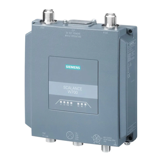
Description of the device 4.1 Device view Device view ① LED display ② R1A1 antenna connector, female N-Connect type ③ Screw-down cover: - for the reset button and - for the PLUG slot (CLP) ④ R2A1 antenna connector, female N-Connect type ⑤... -
Page 19: Components Of The Product
– 1 x digital input/digital output • One grounding screw Please check that the consignment you have received is complete. If the consignment is incomplete, contact your supplier or your local Siemens office. Note Not included with the product The following components do not ship with the product: •... -
Page 20: Accessories
Description of the device 4.3 Accessories Accessories Technical data subject to change. You will find further information on the range of accessories in the Industry Mall (https:// mall.industry.siemens.com) 4.3.1 Installation Component Description Article number Mounting adapter Adapter for mounting on a 35mm DIN rail... -
Page 21: Industrial Ethernet
Description of the device 4.3 Accessories 4.3.3 Industrial Ethernet Cables Industrial Ethernet (pre-assembled) Component Description Article number IE TP Cord M12-180/RJ45-180 IE Flexible Cable, with 1 x M12 plug (X-co‐ ded) 180 degree cable outlet and 1 x RJ45 plug; 180 degree cable outlet Length 0.5m 6XV1878-5TE50 Length 1m... -
Page 22: Digital Input / Digital Output
Description of the device 4.3 Accessories M12 plug-in connector Industrial Ethernet Component Description Article number IE FC M12 PLUG PRO 4x2 M12 data plug-in connector for IE FC TP cables 4x2, IP65/67, X-coded, axial cable outlet 1 connector per package 6GK1901-0DB30-6AA0 8 connectors per package 6GK1901-0DB30-6AA8... -
Page 23: Power Supply
Description of the device 4.3 Accessories M12 plug-in connector digital input / digital output Component Description Article number Control M12 Plug PRO Control M12 Plug PRO; field-assembled 6GK1908-0DB10-6AA0 connector for connecting IO-Link sensors/ actuators; 5-pin; A-coded Pack of 1 4.3.5 Power supply Power cables (pre-assembled) Component... -
Page 24: Flexible Connecting Cables And Antennas
Description of the device 4.3 Accessories Cabinet feedthrough Component Description Article number IE M12 Panel Feedthrough 4x Cabinet feedthrough for conversion from 6GK1901-0DM40-2AA5 M12 connector technology (X-coded, IP65/67) to RJ-45 connector technology (X- coded, IP20) pack of 5 N-Connect/N-Connect Fe‐ Panel feedthrough for wall thicknesses up 6GK5798-2PP00-2AA6 male/Female Panel Feed‐... -
Page 25: Lightning Protection
Description of the device 4.3 Accessories Flexible connecting cable N-Connect/N-Connect Flexible connecting cable for connecting an antenna to a SCALANCE W device with N-Connect connectors. Preassembled with two N male connectors: Length Article number 6XV1875-5AH10 6XV1875-5AH20 6XV1875-5AH50 10 m 6XV1875-5AN10 For railway applications, the following connecting cable are available: Length Article number... -
Page 26: Terminating Resistor
When you select an antenna, keep in mind: • The antennas with national approval for your device You can find additional information on this at (https://www.siemens.com/wireless-approvals). • The country-specific and channel-dependent maximum permissible antenna gain You can find additional information on this in the reference document "Approvals for SCALANCE W700 802.11ax". - Page 27 Description of the device 4.3 Accessories Type Properties Article number ANT793-8DL Directional antenna vertical-horizontal polar‐ 6GK5793-8DL00-0AA0 ized, 5 GHz, 14dBi, IP66, 2 x N-Connector fe‐ male ANT793-8DP Directional antenna, mast/wall mounting, 6GK5793-8DP00-0AA0 13 / 13.5 dBi 4.9 GHz and 5 GHz, N-Connect female ANT795-4MX Omnidirectional antenna, 2/2.5 dBi, 2.4 GHz...
-
Page 28: Led Display
Description of the device 4.4 LED display LED display Information on operating status and data transfer On the front of the housing, several LEDs provide information on the operating status of the device: Color Meaning Power supply L1 too low. Green Power supply L1 is applied. - Page 29 Description of the device 4.4 LED display Color Meaning There is no connection over the Ethernet interface P1. Green There is a connection over the Ethernet interface P1 (link). Flashing green and Data transfer over the Ethernet interface P1. yellow The WLAN interface 1 is deactivated.
- Page 30 Description of the device 4.4 LED display Color Meaning No fault/error. Yellow: Sleep mode is active. The device is booting, an error has occurred or the bootloader is waiting for a new firmware file, which you can load via TFTP, see "Loading new firmware via TFTP without WBM and CLI (Page 61)".
- Page 31 Description of the device 4.4 LED display Note Primary user (radar) on all enabled channels If the device detects a primary user (for example radar signals) on all enabled channels of the WLAN interface, the LED F is lit and R1 flashes. No data traffic is then possible for the next 30 minutes.
-
Page 32: Reset Button
Description of the device 4.5 Reset button Reset button Position NOTICE Loss of water and dust protection If the cover is not mounted correctly, the device is not water and dust proof. ① The reset button is located behind the screw-down cover on the top of the housing. ①... -
Page 33: Mounting
Mounting Safety notices When installing the device, keep to the safety notices listed below. CAUTION Minimum distance to antennas Fit the device so that there is a minimum clearance of 20 cm between antennas and persons. WARNING If a device is operated in an ambient temperature of more than 50 °C, the temperature of the device housing may be higher than 70 °C. - Page 34 Mounting WARNING EXPLOSION HAZARD Replacing components may impair suitability for Class 1, Division 2 or Zone 2. General notes on use according to ATEX and IECEx WARNING To comply with EU Directive 2014/34 EU (ATEX 114), UK-Regulation SI 2016/1107 or the conditions of IECEx or CCC-Ex, the housing or cabinet must meet the requirements of at least IP54 (according to EN/IEC 60529, GB/T 4208) in compliance with EN IEC/IEC 60079‑7, GB 3836.8.
- Page 35 Mounting WARNING Wall mounting outside of the control cabinet or housing does not fulfill the requirements of the FM approval. Note You must not install the device on a wall in hazardous areas. Safety notices when using the device as industrial control equipment according to UL 61010-2-201 If you use the device under UL 61010-2-201 conditions you must also keep to the following safety notices in addition to the general safety notices for protection against explosion:...
-
Page 36: Types Of Installation
Mounting 5.1 Types of installation Types of installation Note The device is only approved for operation in closed rooms. Note the following environmental conditions. Antennas, in particular directional antennas, must be mounted in keeping with their characteristics (refer to the technical specifications of the antenna --> Radiation pattern diagrams). -
Page 37: Wall Mounting
Mounting 5.2 Wall mounting Wall mounting Note Depending on the mounting surface, use suitable fittings. Note The wall mounting must be capable of supporting at least four times the weight of the device. To mount the device on a wall, follow the steps below: 1. -
Page 38: Mounting On Vesa Bracket
Mounting 5.3 Mounting on VESA bracket Mounting on VESA bracket For mounting the device on the VESA 75 x 75 mm wall holder, 4x M4 threaded holes with a thread depth of 8.5 mm are provided on the back of the device, see the "Dimension drawing (Page 69)"... -
Page 39: Din Rail Mounting
Mounting 5.4 DIN rail mounting DIN rail mounting 5.4.1 Installation with the DIN rail mounting adapter The DIN rail mounting adapter is not included with the product, see Accessories (Page 20). Mounting 1. Screw (M3 x 8, tightening torque 0.8 Nm) the DIN rail mounting adapter onto the rear of the device. - Page 40 Mounting 5.4 DIN rail mounting 3. Press the device against the DIN rail until the DIN rail slider catch locks in place. 4. Connect the power supply, refer to the section "Power supply (Page 50)". 5. Fit the antennas, refer to the section "Antennas (Page 53)". Uninstalling 1.
-
Page 41: Mounting With Bracket Support
Mounting 5.4 DIN rail mounting 4. Tilt the device forward and remove the device from the DIN rail. 5. Loosen the screws of the DIN rail mounting adapter completely. 5.4.2 Mounting with bracket support With the bracket support the device can be mounted on a DIN rail rotated through 90° SCALANCE WxM766 Operating Instructions, 07/2021, C79000-G8976-C617-02... - Page 42 Mounting 5.4 DIN rail mounting The DIN rail mounting adapter and bracket holder are not included with the product, see Accessories (Page 20). Mounting 1. Screw (M4 x 20, tightening torque 1.8 Nm) the angle bracket onto the rear of the device. 2.
- Page 43 Mounting 5.4 DIN rail mounting 4. Connect the power supply, refer to the section "Power supply". 5. Fit the antennas, refer to the section "Antennas". Uninstalling 1. Turn off the power to the device. 2. Disconnect all connected cables. 3. Pull the DIN rail slider down with a screwdriver 4.
- Page 44 Mounting 5.4 DIN rail mounting SCALANCE WxM766 Operating Instructions, 07/2021, C79000-G8976-C617-02...
-
Page 45: Connection
Connection Safety notices When connecting up the device, keep to the safety notices listed below. WARNING EXPLOSION HAZARD Replacing components may impair suitability for Class 1, Division 2 or Zone 2. WARNING EXPLOSION HAZARD Do not open the device when the supply voltage is turned on. Note Close unused sockets Close all unused M12 sockets with protective caps (tightening torque at least 0.4 Nm) to achieve... - Page 46 Connection WARNING Danger due to lightning strikes Installing this lightning protector between an antenna and a SCALANCE W device is not adequate protection against a lightning strike. The LP798-1N lightening protector only works within the framework of a comprehensive lightning protection concept. If you have questions, ask a qualified specialist company.
- Page 47 Connection If you use the device under UL 61010-2-201 conditions you must also keep to the following safety notices in addition to the general safety notices for protection against explosion: NOTICE Suitable fusing for the power supply cable The current at the connecting terminals must not exceed 3 A. Use a fuse for the power supply that protects against currents >...
- Page 48 Connection NOTICE Damage to the device due to potential differences To fully eliminate the influence of electromagnetic interference, the device must be grounded. There must be no potential difference between the following parts, otherwise the device or other connected device could be severely damaged: •...
- Page 49 Connection WARNING At an ambient temperature of more than 60 °C, use heat-resistant cables designed for an ambient temperature at least 20 °C higher. The cable entries used on the enclosure must comply with the IP degree of protection required by EN IEC / IEC 60079-0, GB 3836.1. General notes on use in hazardous areas according to UL-HazLoc WARNING WARNING - EXPLOSION HAZARD -...
-
Page 50: Power Supply
Connection 6.1 Power supply Power supply Note Galvanic isolation of the power supply unit To ensure dielectric strength according to IEEE 802.3, the supplying 24 V power supply unit must be galvanically isolated with a dielectric strength of 1500 VAC. The galvanic isolation must also not be bridged by other devices connected to the same power supply unit. - Page 51 Connection 6.1 Power supply Position and pin assignment ① M12 Ethernet interface P1 LAN PoE, X-coded, 8-pin The power can also be supplied via this interface (Power over Ethernet). Pin assignment, see Ethernet (Page 52) ② M12 interface, direct infeed, L-coded, 4-pin The four-pin M12 socket has the following pin assignment: Signal Assignment...
-
Page 52: Ethernet
Connection 6.2 Ethernet Ethernet For connection to Industrial Ethernet at 10/100/1000 Mbps, the device has an M12 interface: X- coded, 8-pin. The power can also be supplied via this interface (Power over Ethernet) Position and pin assignment Assignment Connecting Ethernet ports 1. -
Page 53: Antenna Connector
Connection 6.3 Antenna connector Antenna connector The SCALANCE WxM 766-1 has two antenna connectors of the female N-Connector type. Figure 6-1 Antenna connectors ① Antenna connector R1 A1 ② Antenna connector R1 A2 Procedure Follow the steps below to connect a cable for an external antenna: 1. - Page 54 Connection 6.3 Antenna connector NOTICE UL approval only for use in buildings Within the area of authority of the NEC and CEC, the SCALANCE WxM766-1 devices and the antennas connected to them may only be used in a closed building. For this reason, do not lead antennas into the outdoor area if you need to meet UL or CSA requirements.
-
Page 55: Grounding
Connection 6.4 Grounding Grounding EMC disturbances are diverted to ground via the functional ground. This ensures the immunity of the data transmission. The grounding screw is identified by the following symbol for the functional ground Protective earth/functional ground The connection of the reference potential surface with the protective earth system is normally in the cabinet close to the power feed-in. -
Page 56: Digital Input/Output
Connection 6.5 Digital input/output Digital input/output The device features a digital input and output (M12 A-coded). CAUTION Damage due to voltage being too high or too low The voltage at the digital input/output must not exceed 30 VDC and not fall below -30 VDC, otherwise the digital input/output will be destroyed. -
Page 57: Inserting/Removing The Plug
Connection 6.6 Inserting/removing the PLUG Inserting/removing the PLUG The CLP (Configuration License PLUG) is used to transfer the configuration of the old device to the new device when a device is replaced. The CLP is also referred to as PLUG in the description. The PLUG is available in the following variants: •... - Page 58 Connection 6.6 Inserting/removing the PLUG Position The PLUG slot is on the top of the device housing under a cover, see Reset key. Inserting the PLUG Follow the steps below to insert a PLUG in the device: 1. Turn off the power to the device. 2.
- Page 59 Connection 6.6 Inserting/removing the PLUG Removing the PLUG Follow the steps below to remove a PLUG from the device: 1. Turn off the power to the device. ③ ② 2. Loosen the screws of the slot cover and remove the slot cover .
- Page 60 Connection 6.6 Inserting/removing the PLUG SCALANCE WxM766 Operating Instructions, 07/2021, C79000-G8976-C617-02...
-
Page 61: Upkeep And Maintenance
Upkeep and maintenance Downloading new firmware using TFTP without WBM and CLI You can download new firmware to the device using TFTP. To do this, the device does not need to be reachable either using Web Based Management (WBM) or using the Command Line Interface (CLI). -
Page 62: Restoring The Factory Settings
Upkeep and maintenance 7.2 Restoring the factory settings Restoring the factory settings NOTICE Previous settings If you reset, all the settings you have made will be overwritten by factory defaults. NOTICE Inadvertent reset An inadvertent reset can cause disturbances and failures in a configured network with further consequences. - Page 63 Upkeep and maintenance 7.2 Restoring the factory settings Via the configuration You will find detailed information on resetting the device parameters using the WBM and CLI in the configuration manuals: • Web Based Management, section "Restart" • Command Line Interface, section "Reset and Defaults" SCALANCE WxM766 Operating Instructions, 07/2021, C79000-G8976-C617-02...
- Page 64 Upkeep and maintenance 7.2 Restoring the factory settings SCALANCE WxM766 Operating Instructions, 07/2021, C79000-G8976-C617-02...
-
Page 65: Technical Specifications
Technical specifications The following technical specifications apply to the following devices: • SCALANCE WAM766‑1 • SCALANCE WAM766‑1 EEC • SCALANCE WUM766‑1 Note You will find detailed information on the transmit power and receiver sensitivity in the document "Performance data SCALANCE W700 802.11ax" on the supplied data storage medium (NW_W700ax-RadioInterface_*.pdf). - Page 66 Technical specifications Technical specifications Antenna connector Quantity Design N-Connect socket Impedance 50 Ω nominal Permitted antenna wire lengths < 30 m Frequency range 2412 ... 2480 MHz 4920 ... 5875 MHz Electrical data Direct 24 VDC supply Supply voltage from socket 24 VDC Safe Extra Low Voltage (SELV) Type of current Permitted...
- Page 67 Technical specifications Technical specifications Ambient temperature During op‐ Non-EEC variant -30 °C ... +60 °C eration EEC variant -30 ℃ to +75 ℃ During storage -40 ℃ to +85 ℃ During transportation -40 ℃ to +85 ℃ Relative humidity During operation ≤...
- Page 68 Technical specifications SCALANCE WxM766 Operating Instructions, 07/2021, C79000-G8976-C617-02...
-
Page 69: Dimension Drawing
Dimension drawing Note CAx data You can find the CAx data on the Internet at (https://www.automation.siemens.com/bilddb/ index.aspx?lang=en) 1. Click on the "CAx data" link in the "Direct Links" area. The Industry Image Database page is loaded. 2. Enter the name or article number of the product in the search filter. - Page 70 Dimension drawing Width, height and dimensions for wall mounting Side view SCALANCE WxM766 Operating Instructions, 07/2021, C79000-G8976-C617-02...
- Page 71 Dimension drawing Rear view Rear view with bore holes for VESA bracket 75 x 75, 4x M4, thread depth 8.5 mm See also Wall mounting (Page 37) Mounting on VESA bracket (Page 38) SCALANCE WxM766 Operating Instructions, 07/2021, C79000-G8976-C617-02...
- Page 72 Dimension drawing SCALANCE WxM766 Operating Instructions, 07/2021, C79000-G8976-C617-02...
-
Page 73: Approvals
Approvals You will find the approvals of the products in the reference work "Approvals SCALANCE W700 802.11ax" on the Internet pages of the Siemens Industry Online Support: • Using the search function at Siemens Industry Online Support (https:// support.industry.siemens.com/cs/ww/en/) • Using the search function at Industrial communication (https:// support.industry.siemens.com/cs/ww/en/ps/15859/cert) - Page 74 Approvals SCALANCE WxM766 Operating Instructions, 07/2021, C79000-G8976-C617-02...
-
Page 75: Index
Index A-coded, 50 Interfaces, 65, 66, 67 Antenna cables, 24 Antennas, 24 Connectors, 53 LED display, 28 Lightning protection, 45 Button Reset, 32 Power supply Connecting up, 50 Primary user (radar), 28 Cables Protective caps, 19 Permitted lengths, 65, 66, 67 CAx data, 69 Components of the product, 19 Configuration manuals, 63... - Page 76 Index SCALANCE WxM766 Operating Instructions, 07/2021, C79000-G8976-C617-02...
Need help?
Do you have a question about the SIMATIC NET SCALANCE W M766 Series and is the answer not in the manual?
Questions and answers