Table of Contents
Advertisement
Quick Links
Advertisement
Table of Contents

Subscribe to Our Youtube Channel
Related Manuals for Siemens SIMATIC NET SCALANCE X-100 Series


Summary of Contents for Siemens SIMATIC NET SCALANCE X-100 Series
- Page 1 Introduction Network topologies Product properties SIMATIC NET Installation, connecting up, sources of problems Industrial Ethernet SCALANCE X-100 Approvals and markings Technical specifications Operating Instructions References Dimension drawings A2B00060666D...
- Page 2 Note the following: WARNING Siemens products may only be used for the applications described in the catalog and in the relevant technical documentation. If products and components from other manufacturers are used, these must be recommended or approved by Siemens. Proper transport, storage, installation, assembly, commissioning, operation and maintenance are required to ensure that the products operate safely and without any problems.
-
Page 3: Table Of Contents
Table of contents Introduction..............................5 Network topologies ............................ 9 Product properties ........................... 11 Overview of the product characteristics..................11 Components of the product......................12 Unpacking and checking......................12 SCALANCE X104-2 ........................13 3.4.1 SCALANCE X104-2 product characteristics................13 3.4.2 SCALANCE X104-2 TP ports ......................14 3.4.3 SCALANCE X104-2 FO ports ......................15 SCALANCE X106-1 ........................17 3.5.1... - Page 4 Table of contents Connecting up ..........................45 4.2.1 Power supply..........................45 4.2.2 Signaling contact......................... 46 4.2.3 Grounding............................ 47 4.2.4 Fitting the IE FC RJ-45 Plug 180 ....................48 Possible sources of problems and how to deal with them ............50 Approvals and markings ..........................
-
Page 5: Introduction
Introduction Overview This chapter provides you with an overview of the functions of the unmanaged Industrial Ethernet switches of the SCALANCE X-100 product line. Purpose of the Commissioning Manual This commissioning manual supports you when commissioning networks with the Industrial Ethernet switches of the SCALANCE X-100 product line. - Page 6 Introduction Standards and approvals The Industrial Ethernet switches of the SCALANCE X-100 product line meet the requirements for the CE, UL, C-Tick, FM and ATEX marks. You will find detailed information in the section "Approvals and Markings" in this commissioning manual in the "Approvals" table.
- Page 7 Introduction Overview of the SCALANCE X product family The SCALANCE X-100 product family is part of the SCALANCE X product family. Below, you will find a brief overview of this product family. The SCALANCE X family comprises various product lines that complement each other and that are carefully tuned to specific automation tasks.
- Page 8 Introduction By supporting IT standards, for example, VLAN, RSTP, Layer 3, automation networks can be seamlessly connected to existing corporate networks. The SCALANCE X-400 switches are ideally suited, for example, to process control systems such as PCS 7. SCALANCE X-100 Operating Instructions, 04, A2B00060666D...
-
Page 9: Network Topologies
Network topologies Switching technology allows extensive networks to be set up with numerous nodes and simplifies network expansion. Which topologies can be implemented? Using the Industrial Ethernet switches of the SCALANCE X-100 product line, you can implement bus and star topologies. Note Make sure that the maximum permitted cable lengths for the relevant devices are not exceeded. - Page 10 Network topologies Star topology Figure 2-2 Electrical star topology. Example with SCALANCE X124 Figure 2-3 Electrical/optical star topology. Example with SCALANCE X112-2 and SCALANCE X104-2 SCALANCE X-100 Operating Instructions, 04, A2B00060666D...
-
Page 11: Product Properties
Product properties Overview of the product characteristics Table 3- 1 Overview of the product characteristics Device type SCALANCE X104-2 X10⁶-1 X108 X108PoE X112-2 X116 X124 SIMATIC environment Diagnostics LED 24 V DC Compact housing (securing collar, etc.) 2x 24 V DC Signaling contact + on-site operation Diagnostics: Web, SNMP,... -
Page 12: Components Of The Product
Product properties 3.2 Components of the product Components of the product The Industrial Ethernet switches of the SCALANCE X-100 product line always ship with a 2- pin and a 4-pin terminal block, a product information pamphlet and a CD. The CD contains the operating instructions. -
Page 13: Scalance X104-2
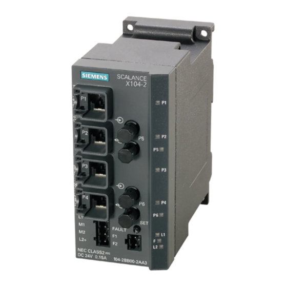
Product properties 3.4 SCALANCE X104-2 SCALANCE X104-2 3.4.1 SCALANCE X104-2 product characteristics Possible connections The SCALANCE X104-2 has four RJ-45 jacks and two BFOC ports for the connection of end devices or other network segments. Note The BFOC socket (Bayonet Fiber Optic Connector) corresponds to the ST socket. Figure 3-1 SCALANCE X104-2 SCALANCE X-100... -
Page 14: Scalance X104-2 Tp Ports
Product properties 3.4 SCALANCE X104-2 3.4.2 SCALANCE X104-2 TP ports Connector pinout On the SCALANCE X104-2, the TP ports are implemented as RJ-45 jacks with MDI-X assignment (Medium Dependent Interface–Autocrossover) of a network component. Figure 3-2 RJ-45 jack Table 3- 3 Pin assignment of the RJ-45 jack Pin number Assignment... -
Page 15: Scalance X104-2 Fo Ports
Product properties 3.4 SCALANCE X104-2 Autonegotiation Autonegotiation means the automatic detection of the functionality of the port at the opposite end. Using autonegotiation, repeaters or end devices can detect the functionality available at the port of a partner device allowing automatic configuration of different types of device. With autonegotiation, two components connected to a link segment can exchange parameters and set themselves to match the supported communication functionality. - Page 16 Product properties 3.4 SCALANCE X104-2 Since the full duplex mode and the transmission rate cannot be modified for optical transmission, autonegotiation cannot be selected. Transmission medium Data transmission is over multimode fiber-optic cable (FOC). The wavelength is 1310 nm. Multimode fiber-optic cables are used with a core of 50 or 62.5 µm; the light source is an LED.
-
Page 17: Scalance X106-1
Product properties 3.5 SCALANCE X106-1 SCALANCE X106-1 3.5.1 SCALANCE X106-1 product characteristics Possible connections The SCALANCE X106-1 has six RJ-45 jacks and a BFOC port for the connection of end devices or other network segments. Note The BFOC socket (Bayonet Fiber Optic Connector) corresponds to the ST socket. Figure 3-3 SCALANCE X106-1 SCALANCE X-100... -
Page 18: Scalance X106-1 Tp Ports
Product properties 3.5 SCALANCE X106-1 3.5.2 SCALANCE X106-1 TP ports Connector pinout On the SCALANCE X106-1, the TP ports are implemented as RJ-45 jacks with MDI-X assignment (Medium Dependent Interface–Autocrossover) of a network component. Figure 3-4 RJ-45 jack Table 3- 4 Pin assignment of the RJ-45 jack Pin number Assignment... -
Page 19: Scalance X106-1 Fo Port
Product properties 3.5 SCALANCE X106-1 Autonegotiation Autonegotiation means the automatic detection of the functionality of the port at the opposite end. Using autonegotiation, repeaters or end devices can detect the functionality available at the port of a partner device allowing automatic configuration of different types of device. With autonegotiation, two components connected to a link segment can exchange parameters and set themselves to match the supported communication functionality. - Page 20 Product properties 3.5 SCALANCE X106-1 Since the full duplex mode and the transmission rate cannot be modified for optical transmission, autonegotiation cannot be selected. Transmission medium Data transmission is over multimode fiber-optic cable (FOC). The wavelength is 1310 nm. Multimode fiber-optic cables are used with a core of 50 or 62.5 µm; the light source is an LED.
-
Page 21: Scalance X108
Product properties 3.6 SCALANCE X108 SCALANCE X108 3.6.1 SCALANCE X108 product characteristics Possible connections The SCALANCE X108 has eight RJ-45 jacks for the connection of end devices or other network segments. Figure 3-5 SCALANCE X108 SCALANCE X-100 Operating Instructions, 04, A2B00060666D... -
Page 22: Scalance X108 Tp Ports
Product properties 3.6 SCALANCE X108 3.6.2 SCALANCE X108 TP ports Connector pinout On the SCALANCE X108, the TP ports are implemented as RJ-45 sockets with MDI-X assignment (Medium Dependent Interface–Autocrossover) of a network component. Figure 3-6 RJ-45 jack Table 3- 5 Pin assignment of the RJ-45 jack Pin number Assignment... - Page 23 Product properties 3.6 SCALANCE X108 Autonegotiation Autonegotiation means the automatic detection of the functionality of the port at the opposite end. Using autonegotiation, repeaters or end devices can detect the functionality available at the port of a partner device allowing automatic configuration of different types of device. With autonegotiation, two components connected to a link segment can exchange parameters and set themselves to match the supported communication functionality.
-
Page 24: Scalance X108Poe
Product properties 3.7 SCALANCE X108PoE SCALANCE X108PoE 3.7.1 SCALANCE X108 PoE product characteristics Possible connections The SCALANCE X108 PoE has eight RJ-45 jacks for the connection of end devices or other network segments. Figure 3-7 SCALANCE X108PoE 3.7.2 SCALANCE X108 PoE TP ports Connector pinout Note To supply PoE end devices with power, 4- or 8-wire connecting cables (complying with IEEE... - Page 25 Product properties 3.7 SCALANCE X108PoE Over and above the pure Ethernet functionality, ports 1 and 2 can also be used to supply power to Power-over-Ethernet end devices (for example SCALANCE-W) in compliance with 802.3af. The two ports providing PoE are supplied from the same power source. This means that they are electrically interconnected.
- Page 26 Product properties 3.7 SCALANCE X108PoE Autonegotiation Autonegotiation means the automatic detection of the functionality of the port at the opposite end. Using autonegotiation, repeaters or end devices can detect the functionality available at the port of a partner device allowing automatic configuration of different types of device. With autonegotiation, two components connected to a link segment can exchange parameters and set themselves to match the supported communication functionality.
-
Page 27: Scalance X112-2
Product properties 3.8 SCALANCE X112-2 SCALANCE X112-2 3.8.1 SCALANCE X112-2 product characteristics Possible connections The SCALANCE X112-2 has twelve RJ-45 jacks and two BFOC ports for the connection of end devices or other network segments. Note The BFOC socket (Bayonet Fiber Optic Connector) corresponds to the ST socket. Figure 3-9 SCALANCE X112-2 SCALANCE X-100... -
Page 28: Scalance X112-2 Tp Ports
Product properties 3.8 SCALANCE X112-2 3.8.2 SCALANCE X112-2 TP ports Connector pinout On the SCALANCE X112-2, the TP ports are implemented as RJ-45 jacks with MDI-X assignment (Medium Dependent Interface–Autocrossover) of a network component. Figure 3-10 RJ-45 jack Table 3- 7 Pin assignment of the RJ-45 jack Pin number Assignment... -
Page 29: Scalance X112-2 Fo Ports
Product properties 3.8 SCALANCE X112-2 Autonegotiation Autonegotiation means the automatic detection of the functionality of the port at the opposite end. Using autonegotiation, repeaters or end devices can detect the functionality available at the port of a partner device allowing automatic configuration of different types of device. With autonegotiation, two components connected to a link segment can exchange parameters and set themselves to match the supported communication functionality. - Page 30 Product properties 3.8 SCALANCE X112-2 Since the full duplex mode and the transmission rate cannot be modified for optical transmission, autonegotiation cannot be selected. Transmission medium Data transmission is over multimode fiber-optic cable (FOC). The wavelength is 1310 nm. Multimode fiber-optic cables are used with a core of 50 or 62.5 µm; the light source is an LED.
-
Page 31: Scalance X116
Product properties 3.9 SCALANCE X116 SCALANCE X116 3.9.1 SCALANCE X116 product characteristics Possible connections The SCALANCE X116 has 16 RJ-45 jacks for the connection of end devices or other network segments. Figure 3-11 SCALANCE X116 SCALANCE X-100 Operating Instructions, 04, A2B00060666D... -
Page 32: Scalance X116 Tp Ports
Product properties 3.9 SCALANCE X116 3.9.2 SCALANCE X116 TP ports Connector pinout On the SCALANCE X116, the TP ports are implemented as RJ-45 jacks with MDI-X assignment (Medium Dependent Interface–Autocrossover) of a network component. Figure 3-12 RJ-45 jack Table 3- 8 Pin assignment of the RJ-45 jack Pin number Assignment... - Page 33 Product properties 3.9 SCALANCE X116 Autonegotiation Autonegotiation means the automatic detection of the functionality of the port at the opposite end. Using autonegotiation, repeaters or end devices can detect the functionality available at the port of a partner device allowing automatic configuration of different types of device. With autonegotiation, two components connected to a link segment can exchange parameters and set themselves to match the supported communication functionality.
-
Page 34: Scalance X124
Product properties 3.10 SCALANCE X124 3.10 SCALANCE X124 3.10.1 SCALANCE X124 product characteristics Possible connections The SCALANCE X124 has 24 RJ-45 jacks for the connection of end devices or other network segments. Figure 3-13 SCALANCE X124 SCALANCE X-100 Operating Instructions, 04, A2B00060666D... -
Page 35: Scalance X124 Tp Ports
Product properties 3.10 SCALANCE X124 3.10.2 SCALANCE X124 TP ports Connector pinout On the SCALANCE X124, the TP ports are implemented as RJ-45 sockets with MDI-X assignment (Medium Dependent Interface–Autocrossover) of a network component. Figure 3-14 RJ-45 jack Table 3- 9 Pin assignment of the RJ-45 jack Pin number Assignment... - Page 36 Product properties 3.10 SCALANCE X124 Autonegotiation Autonegotiation means the automatic detection of the functionality of the port at the opposite end. Using autonegotiation, repeaters or end devices can detect the functionality available at the port of a partner device allowing automatic configuration of different types of device. With autonegotiation, two components connected to a link segment can exchange parameters and set themselves to match the supported communication functionality.
-
Page 37: Scalance X-100 Button
Product properties 3.11 SCALANCE X-100 button 3.11 SCALANCE X-100 button What does the button do? Using the button, you can display and modify the set fault mask. The fault mask setting is retained after device power off/on. After pressing and holding down the button, the currently valid fault mask is displayed for approximately 3 seconds. -
Page 38: Displays
Product properties 3.12 Displays 3.12 Displays 3.12.1 Fault indicator (red LED) Fault indicator (red LED) If the red LED is lit, the SCALANCE X-100 has detected a problem. The signaling contact opens at the same time. The LED signals that the device can adopt the following statuses: Device type SCALANCE LED lit red LED not lit... -
Page 39: Port Status Indicator (Green/Yellow Leds)
Product properties 3.12 Displays Device type Green LED lit LED not lit SCALANCE X104-2 X10⁶-1 X108 X108PoE X112-2 X116 X124 1. Power supply L1 or L2 is connected. 2. Power supply L1 and/or L2 not connected or <14 V. 3.12.3 Port status indicator (green/yellow LEDs) Port status indicator (green/yellow LEDs) The LEDs signal that the device can adopt the following statuses. - Page 40 Product properties 3.12 Displays SCALANCE X-100 Operating Instructions, 04, A2B00060666D...
-
Page 41: Installation, Connecting Up, Sources Of Problems
Installation, connecting up, sources of problems Assembly Types of installation The Industrial Ethernet switches of the SCALANCE X-100 product line can be mounted in different ways: ● Installation on a 35 mm DIN rail ● Installation on a SIMATIC S7-300 standard rail ●... -
Page 42: Installation On A Din Rail
Installation, connecting up, sources of problems 4.1 Assembly If a device of the SCALANCE X-100 product line is operated at an ambient temperature higher than 55° C, the temperature of the device housing may be higher than 70°C. The subject unit must be located in a Restricted Access Location where access can only be gained by SERVICE PERSONNEL or by USERS who have been instructed about the reasons for the restrictions applied to the location and about any precautions that shall be taken when operated in an air ambient in excess of 55°... -
Page 43: Installation On A Standard Rail
Installation, connecting up, sources of problems 4.1 Assembly Uninstalling To remove the Industrial Ethernet switches of the SCALANCE X-100 product line from the DIN rail: 1. First disconnect all connected cables. 2. Use a screwdriver to release the lower DIN rail catch of the device and pull the lower part of the device away from the rail. -
Page 44: Wall Mounting
Installation, connecting up, sources of problems 4.1 Assembly Uninstalling To remove Industrial Ethernet switches of the SCALANCE X-100 product line from the SIMATIC S7-300 standard rail: 1. First disconnect all connected cables. 2. Loosen the device screws on the underside of the S7 standard rail and lift the device away from the rail. -
Page 45: Connecting Up
Installation, connecting up, sources of problems 4.2 Connecting up Connecting up 4.2.1 Power supply Power supply The power supply is connected using a 4-pin plug-in terminal block. The power supply can be connected redundantly. Both inputs are isolated. There is no distribution of load. -
Page 46: Signaling Contact
Installation, connecting up, sources of problems 4.2 Connecting up WARNING The device is designed for operation with safety extra-low voltage. This means that only safety extra-low voltages (SELV) complying with IEC950/EN60950/ VDE0805 can be connected to the power supply terminals. The power supply unit for the device power supply must meet NEC Class 2, as described by the National Electrical Code(r) (ANSI/NFPA 70). -
Page 47: Grounding
Installation, connecting up, sources of problems 4.2 Connecting up Table 4- 2 Pin assignment of the signaling contact SCALANCE X-100 Pin number Assignment Pin 1 Pin 2 The following errors/faults can be signaled by the signaling contact: ● The failure of a link at a monitored port. ●... -
Page 48: Fitting The Ie Fc Rj-45 Plug 180
Installation, connecting up, sources of problems 4.2 Connecting up 4.2.4 Fitting the IE FC RJ-45 Plug 180 Assembly of the IE FC RJ-45 Plug 180 on an IE FC standard cable For information on assembling an IE FC RJ-45 Plug 180 on a SIMATIC NET Industrial Ethernet FastConnect cable, please refer to the instructions supplied with the IE FC RJ-45 Plug. - Page 49 Installation, connecting up, sources of problems 4.2 Connecting up Removing the IE FC RJ-45 Plug 180 1. Press on the locking mechanism of the IE FC RJ-45 Plug 180 gently to remove the plug. Figure 4-10 Releasing the RJ-45 Plug If there is not enough space to release the lock with your hand, you can also use a 2.5 mm screwdriver.
-
Page 50: Possible Sources Of Problems And How To Deal With Them
If both of the power supplies drop below approximately 14 V, this reduced voltage is indicated by the red fault LED. The L LEDs go off. If a fault develops, please send the device to your SIEMENS service center for repair. Repairs on-site are not possible. -
Page 51: Approvals And Markings
Twisted Pair and Fiber Optic Networks" /1/ when installing and operating the device. Conformity Certificates The EC Declaration of Conformity is available for the responsible authorities according to the above-mentioned EC Directive at the following address: Siemens Aktiengesellschaft Industry Sector Industry Automation Division Industrielle Kommunikation (I IA SC IC) Postfach 4848 D-90026 Nürnberg... - Page 52 Approvals and markings Notes for the Manufacturers of Machines The products are not machines in the sense of the EC Machinery Directive. There is therefore no declaration of conformity relating to the EC Machinery Directive 98/37/EEC for these products. If the products are part of the equipment of a machine, they must be included in the procedure for the declaration of conformity by the manufacturer of the machine.
- Page 53 Approvals and markings Device type c-UL-us c-UL-us for C-TICK ATEX Zone 2 SCALANCE hazardous locations X112-2 UL 1604, UL FM 3611 AS/NZS EN 61000- EN60079-0: 60950-1 2279Pt.15 CL.1, Div.2 2064 6-4, 2006 CL.1, Div.2 GP. (Class A). EN 61000- EN60079-15: C22.2 A.B.C.D T..
- Page 54 Approvals and markings SCALANCE X-100 Operating Instructions, 04, A2B00060666D...
-
Page 55: Technical Specifications
Technical specifications Technical specifications Table 6- 1 Connectors Device type Attachment of end Connecting end devices Connector for power Connector for SCALANCE devices or network or network components supply signaling contact components over over fiber-optic twisted pair X104-2 4 x RJ-45 sockets with 2 x 2 BFOC sockets 1 x 4-pin plug-in 1 x 2-pin plug-in terminal... - Page 56 Technical specifications 6.1 Technical specifications Table 6- 2 Electrical data Device type Power supply Power loss at Current consumption Overcurrent protection at SCALANCE 2 x 24 V DC 24 V DC at rated voltage input PTC resettable fuse (18-32 V DC) (0.6 A / 60 V) Safety extra-low voltage (SELV)
- Page 57 Technical specifications 6.1 Technical specifications Table 6- 5 Permitted cable lengths (fiber-optic) Device type 1 - 50 m 1 - 100 m 0 - 3,000 m 0 - 26000 m SCALANCE 980/1000 200/230 polymer glass FOC glass FOC plastic optical cladded fiber (PCF) 62.5/125 µm or 10/125 µm single mode fiber;...
- Page 58 Technical specifications 6.1 Technical specifications Device type Operating temperature Storage/transport Relative Operating altitude at max. SCALANCE temperature humidity in xx°C ambient temperature operation X108PoE -20 to +60° C -40 to +80° C ‹ 95 % 2000 m at max. 56° C 3000 m at max.
- Page 59 Technical specifications 6.1 Technical specifications Note The number of SCALANCE X Industrial Ethernet Switches connected in a line influences the frame propagation time. When a frame passes through devices of the SCALANCE X-100 product line, it is delayed by the store and forward function of the switch •...
- Page 60 Technical specifications 6.1 Technical specifications SCALANCE X-100 Operating Instructions, 04, A2B00060666D...
-
Page 61: References
References Sources of information and other documentation 1. SIMATIC NET Industrial Twisted Pair and Fiber-Optic Networks, Order numbers: 6GK1970-1BA10-0AA0 German 6GK1970-1BA10-0AA1 English 6GK1970-1BA10-0AA2 French 6GK1970-1BA10-0AA4 Italian 2. PROFINET Cabling and Interconnection Technology Guideline Can be ordered from the PROFIBUS User Organization (PNO) SCALANCE X-100 Operating Instructions, 04, A2B00060666D... - Page 62 References SCALANCE X-100 Operating Instructions, 04, A2B00060666D...
-
Page 63: Dimension Drawings
Dimension drawings Dimension Drawing Figure 8-1 Dimension drawing of the SCALANCE X104-2, X106-1, X108, X108PoE SCALANCE X-100 Operating Instructions, 04, A2B00060666D... - Page 64 Dimension drawings 8.1 Dimension Drawing Figure 8-2 Dimension drawing rear view of the SCALANCE X116, X112-2 SCALANCE X-100 Operating Instructions, 04, A2B00060666D...
- Page 65 Dimension drawings 8.1 Dimension Drawing Figure 8-3 Dimension drawing rear view of the SCALANCE X124 SCALANCE X-100 Operating Instructions, 04, A2B00060666D...
- Page 66 Dimension drawings 8.1 Dimension Drawing Figure 8-4 Dimension drawing of the X-100 side view SCALANCE X-100 Operating Instructions, 04, A2B00060666D...
- Page 67 Dimension drawings 8.1 Dimension Drawing Figure 8-5 Bending radiuses and clearances SCALANCE X-100 Operating Instructions, 04, A2B00060666D...
- Page 68 Dimension drawings 8.1 Dimension Drawing SCALANCE X-100 Operating Instructions, 04, A2B00060666D...
-
Page 69: Glossary
Glossary Aging time The aging time is the time after which a learned MAC address is discarded if a SCALANCE X-100 has not received frames with this sender address during this time. Autocrossover Technique with which a TP port is automatically switched over between MDI and MDI-X assignment to make a connection independent of the port assignment of the device being attached. - Page 70 Glossary Monomode See Single mode Multicast A frame with a multicast address is received by all nodes prepared to receive this address. Multimode In multimode transmission, the pulse is transferred using many modes (waves) that travel along curved paths or are reflected within the core. Attenuation is mainly caused by physical absorption and dispersion as well as by mechanical bending.
- Page 71 Glossary Single mode In single mode transmission, (and monomode transmission) the pulse is transmitted by a straight mode (wave). Attenuation is mainly caused by physical absorption and dispersion as well as by mechanical bending. The amount of attenuation depends, among other things, on the wavelength of the input light.
- Page 72 Glossary SCALANCE X-100 Operating Instructions, 04, A2B00060666D...
-
Page 73: Index
Index ATEX, 6 FM approval, 6 ATEX95, 6 Autonegotiation, 16, 20, 24, 27, 30, 34, 37 MDI /MDIX autocrossover function, 16, 20, 24, 27, 30, 34, 37 Bending radiuses, 67 BFOC socket ST socket, 18 Button, 38 Network topology, 9 Bus topology, 9 Star topology, 10 Certifications and approvals, 6, 52... - Page 74 Index UL approval, 6 SCALANCE X-100 Operating Instructions, 04, A2B00060666D...
Need help?
Do you have a question about the SIMATIC NET SCALANCE X-100 Series and is the answer not in the manual?
Questions and answers