Table of Contents
Advertisement
Quick Links
Installation
Instructions
Product: Steering Brace System™
Part Number: PN OGS960 / OGS962
Application: Jeep® Cherokee XJ, 1984-01
Welcome
CONGRATULATIONS on your purchase of a
new JKS Steering Brace System! At JKS
Manufacturing, we are committed to providing
you with the best products available and your
satisfaction is our first priority.
READ INSTRUCTIONS THOROUGHLY to
familiarize yourself with the required skills and
tools BEFORE attempting installation.
ATTENTION INSTALLER
Review the front bumper re-
installation section on page 5
BEFORE installing product.
JKS Steering Brace System Installation
Important
INSTALLATION REQUIRES WELDING to the
unibody chassis by a qualified welder or metal
fabricator. A bolt-on installation is not possible
for this product.
CHECK STEERING GEAR TORQUE SPECS
on a regular basis.
Tools Required
Metric/Standard Socket Wrench Set
Torque Wrench
Die Grinder with Sanding/Grinding Wheels
(or similar tool for cleaning chassis)
5/8" Drill Bit, or preferably a Uni-bit
(for enlarging holes in chassis)
Carbide Cutting Tool *
(for enlarging holes in chassis)
3/4" Drill Bit (for new tow hook holes)
C-clamp or Locking Pliers
Hammer *
Factory Service Manual (recommended)
Welding Equipment
Satin Black Spray Paint
* Asterisk denotes tools that are not required for some
applications. Thoroughly read instructions first to
determine which tools will be required for your
application.
PN OGS960 / OGS962
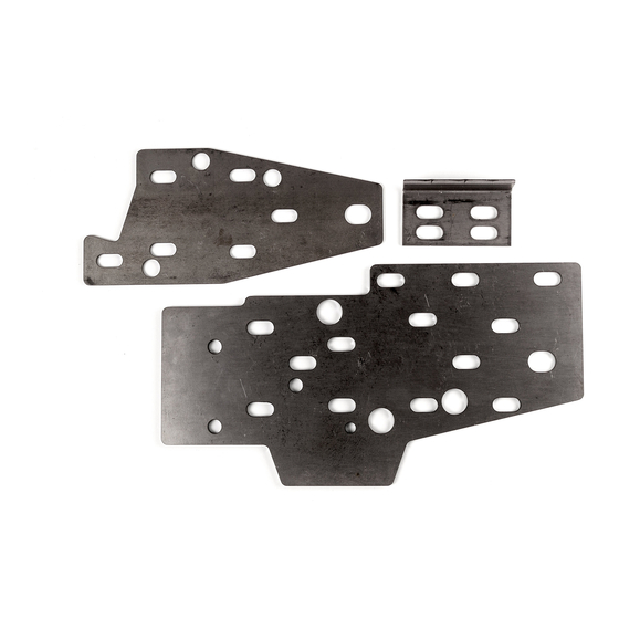
Parts
PN OGS960 pictured
DESCRIPTION
A
Outer Chassis Plate (3/16")
B
Inner Chassis Plate (1/8")
C
Support Sleeves
D
Steering Gear Mounting Bolts
E
Flat Washers
F
Installation Spacers
G
Tow Hook Support Bracket
H
3/4" Solid Rod
HOLE IDENTIFICATION DIAGRAM
QTY
1
1
3
3
3
3
1
1
Page 1 of 5
Advertisement
Table of Contents

Related Manuals for JKS Steering Brace System


Summary of Contents for JKS Steering Brace System
- Page 1 (for enlarging holes in chassis) CONGRATULATIONS on your purchase of a Inner Chassis Plate (1/8”) Carbide Cutting Tool * new JKS Steering Brace System! At JKS Support Sleeves (for enlarging holes in chassis) Manufacturing, we are committed to providing 3/4” Drill Bit (for new tow hook holes)
- Page 2 The following instructions refer to installation of a Enlarge the inboard and outboard mounting single Steering Brace System (PN OGS960) on the holes to approximately 5/8” – or until narrow driver-side chassis rail only. For a dual Steering Brace end of Support Sleeves (C) can be inserted.
- Page 3 HINT: Support Sleeves (C) should protrude through large holes in Outer Chassis Plate (A), but need not be in perfect alignment as any voids surrounding holes will be filled when welded. JKS Steering Brace System Installation PN OGS960 / OGS962 Page 3 of 5...
- Page 4 Once all welding and final sanding/grinding is complete, any bare metal must be painted to prevent corrosion. There should be no exposed metal visible when painted properly. JKS Steering Brace System Installation PN OGS960 / OGS962 Page 4 of 5...
- Page 5 Choose this option if the front bumper will not fit specifications regularly. the reinforced chassis. Modify the bumper mounting bracket to © 2006 JKS Manufacturing, Inc & Aftermarketing, LLC accommodate the additional 3/16” thickness of the Revision Date 4/7/2006 Outer Chassis Plate (A). Install the front bumper...
Need help?
Do you have a question about the Steering Brace System and is the answer not in the manual?
Questions and answers