Advertisement
Advertisement

Subscribe to Our Youtube Channel
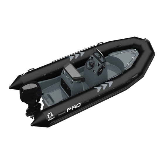
Summary of Contents for Zodiac PRO 500
- Page 1 Owner's Manual Volume 2...
-
Page 2: Table Of Contents
VOLUME 2 DESCRIPTION - BUOYANCY CHAMBER PROPULSION SYSTEM INSTALLATION AND CIRCUITS CONTENTS PAGE I - GENERAL DESCRIPTIONS I-1-Technical characteristics 2 - 3 ---------------------------------------------------------- I-2-Inventory ------------------------------------------------------------------------------- I-3-Location of items --------------------------------------------------------------------- I-4-Handling ------------------------------------------------------------------------------- II - BUOYANCY CHAMBER II-1-Setting up the buoyancy chamber – Main steps ------------------------ II-2-Inflation system-------------------------------------------------------------- 13 - 14... -
Page 3: I-1-Technical Characteristics
DESCRIPTION - Technical characteristics I-1-TECHNICAL CHARACTERISTICS Dimensions 4.70 15‘ 5“ (ft) 3.38 11‘ 1“ (ft) 2.05 6‘ 9“ (ft) 1.05 3‘ 5“ (ft) 0.50 1‘8“ (ft) Design category (Directive 94/25/EC) Capacity (ISO) 1060 Maximum 2337 Compartment Engine configuration Minimum power recommended Maximum power recommended... - Page 4 DESCRIPTION - Technical characteristics Dimension tolerance: +/- 4% NOTE The maximum payload has been calculated according to ISO 6185 standards. Operating at or near maximum payload is only advised in calm water and at reduced speeds. Weight shown not including accessories The recommended power corresponds to optimum operation of the NOTE boat's capabilities for an average load (9 people.)
-
Page 5: I-2-Inventory
DESCRIPTION - Inventory I-2-INVENTORY HULL Polyester hull Counter-moulded non-slip deck 1 Bow ring 1 Anchor locker (capacity approximately 86 litres) 2 traction chain plates 1 Mooring cleat 1 Hull drain hole 1 high flow rate self-bailers with stern well BUOYANCY CHAMBER Removable buoyancy chamber Rails + lashing Easy push valves... -
Page 6: I-3-Location Of Items
DESCRIPTION – Location of items I-3-LOCATION OF ITEMS ITEM DESIGNATION REF. Buoyancy chamber Anchor locker Chain plate Towing chain plates high flow rate self-bailer Hull drain hole Page 6 of 17... - Page 7 Page 7 / 17...
- Page 8 ITEM DESIGNATION REF. Bow roller Anchor locker cover Lashing Handle Mooring cleat Buoyancy chamber AFT Chain plate High flow rate self-bailer Hull drain hole Water shield Easy push valve Tank filler access Page 8 of 17...
-
Page 9: I-4-Handling
DESCRIPTION - Handling I-4-HANDLING I-4-1-Transportation The trailer installation recommendations are specified in VOLUME I of the owner's manual. I-4-2-Storage THE BOAT MUST REST ON THE BOW LINE (SEE SKETCH BELOW). WARNING PRO 9 MAN (dimensions in mm) Page 9 / 17... - Page 10 Remove the aft chain plates and refit them with the ring reversed (facing forward). b- Fit the bow of the boat with 2 additional chain plates (contact your ZODIAC dealer). The diagram below shows the areas where the fore chain plates are located (distances in millimetres).
- Page 11 DESCRIPTION – Location of accessories I-5-1-LOCATION OF OPTIONAL ACCESSORIES I-5-1-1-Console/Seat/Bolster Your boat can accept certain optional accessories (console/seat/bolster). Position them in the locations indicated below to optimise use of the boat. The positioning dimensions are taken from the aft transom (distances in millimetres). Position defined in Intersection...
- Page 12 B- Boarding ladder (recommended position) Page 12 of 17...
-
Page 13: Buoyancy Chamber
BUOYANCY CHAMBER – Main steps II-1-SETTING UP THE BUOYANCY CHAMBER – MAIN STEPS When assembling the boat, it is important that you follow the procedure in the correct order. Proceed step by step, referring each time to the pages indicated for explanations. INFLATION PROCEDURE PAGE SECTION... - Page 14 BOAT INFLATION Activate all valves in the inflation position. Attach the hose connector to the inflator inflation port. To inflate your boat properly, the inflator should be correctly placed on the ground. The boat inflates rapidly if the inflator is used smoothly and without haste.
- Page 15 BUOYANCY CHAMBER - Pressure INFLATING THE BUOYANCY TUBE Place the adapter corresponding to the diameter of the semi built-in valve at the inflator hose nozzle. Inflate the buoyancy mechanism, balancing the pressure between the different compartments until the partitions (a) are no longer visible (pressure = 240 mb) NEVER PUT A COMPARTMENT UNDER PRESSURE...
- Page 16 BUOYANCY CHAMBER - Pressure RISK OF PRESSURE LOSS: Your boat is exposed to direct sunlight on the beach (temperature=50°C) at the EXAMPLE: recommended pressure (240 mb/3.4 PSI). When you launch it (temperature=20°C), the temperature and internal pressure of the inflatable compartments will drop simultaneously (up to 120 mb) and YOU WILL THEN NEED TO REINFLATE until you regain the millibars lost due to the difference between the ambient air and water temperatures.
-
Page 17: Propulsion System
PROPULSION SYSTEM Complies with ZODIAC's recommendations and with the engine manufacturer's recommendations. For optimum use of your boat, seek advice from your dealer. Page 17 / 17...


Need help?
Do you have a question about the PRO 500 and is the answer not in the manual?
Questions and answers