Table of Contents
Advertisement
Available languages
Available languages
Quick Links
Installation Instructions
LiteKeeper® 8
General Information
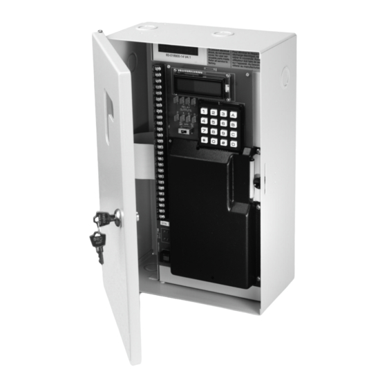
The LiteKeeper 8® is shipped in one package. The relay
card is mounted in the high voltage compartment. The
logic board and inputs are located in the low voltage
compartment. The following information describes the
LiteKeeper® installation. For programming information,
refer to the LiteKeeper® Programming Manual.
Getting Started
1.
Do not discard these installation instructions. Please
keep for future reference and operation information.
2.
The relay cards are protected by shrink-wrap. Leave
shrink-wrap in place until all drilling and metal work is
complete to protect against metal shards getting into
component circuitry.
3.
Always disconnect all power before wiring.
4.
Use only as intended and at the listed voltage.
5.
All installation service must be performed by qualified
personnel or service technicians.
6.
Install in accordance with National Electrical Code
and any other codes that may apply.
7 .
High Voltage is present inside the lighting enclosure.
Use extreme caution when performing maintenance
on this equipment. Failure to follow this warning and
proper safety procedures could result in severe injury
or death and/or damage to the equipment.
8.
Document all wiring that is terminated to the relays
so that the lighting control equipment can be properly
configured and programmed for operation.
9.
It is recommended that all low voltage wiring be
done with power removed to the logic board to
protect components from potential shorts during the
wiring process.
Model# LK8-NO
Model# LK8-LRC
Model# LK8-MRC
Model# LK8-TPRC
Mounting in the Enclosure
1.
Choose a dry location convenient to the circuit
breaker panel.
2.
Mount the panel on a firm surface using pre-drilled
holes.
3.
Connect the enclosure to the circuit breaker panel
using conduit into the punch holes provided.
4.
Remove all cuttings and dirt before removing
shrink-wrap from the relays.
Make certain that high voltage and low voltage
N
otte:
wiring enters the enclosure separately. High
Voltage wiring should be brought into the top or
bottom of the enclosure. Low Voltage wire should
enter in the low voltage wiring compartment on
the left side of the enclosure.
Failure to separate high voltage from low voltage wiring
may cause interference with logic board function.
ON
C
H
+24
1
LITEKEEPER
OFF
12:OO O1/O1/95
ON
C
H
+24
1
OFF
1
3
5
7
1
2
3
A
RELAY
ON
OUTPUTS
C
2
6
8
H
4
+24
4
5
B
1
6
OFF
ON
7
8
9
C
C
H
+24
1
*
0
#
D
OFF
ON
C
H
+24
1
OFF
ON
C
H
+24
1
OFF
ON
C
H
+24
1
OFF
ON
C
H
+24
8
OFF
+24
VDC
DC
GND
Low Voltage Wiring
Compartment
INS #
High Voltage Wiring
Compartment
Low and High Voltage
Advertisement
Table of Contents

Related Manuals for Eaton Greengate LiteKeeper 8


Summary of Contents for Eaton Greengate LiteKeeper 8
- Page 1 Model# LK8-NO Model# LK8-LRC Model# LK8-MRC INS # Installation Instructions Model# LK8-TPRC LiteKeeper® 8 General Information Mounting in the Enclosure The LiteKeeper 8® is shipped in one package. The relay Choose a dry location convenient to the circuit card is mounted in the high voltage compartment. The breaker panel.
- Page 2 Wiring the Transformer Wiring the Transformer Standard Relay Card Notes The Standard Relay Card is rated for single-pole load use only. Connection of 2 pole circuits/loads to the The transformer is multi-tapped and voltages are Standard Relay Card will void the equipment warranty color-coded.
- Page 3 Connecting Relay Loads Latching Relay Card Wiring The latching relay is a simple closure, breaking the line and load wires of a normal circuit. To wire the relay into the control circuit: Line Load Modular Relay Card Connect a 120, 277 or 347 volt, 20 amp maximum, Wiring Diagram Relay Rating: 20Amps 120/277/347 VAC...
- Page 4 Connecting Relay Loads Standard Relay Module Wiring The standard relay is a simple contact closure, breaking the line and load wires of a normal circuit. To wire the relay into Wiring Terminal Relay Status the control circuit: Block Indicator LED Connect a 120 or 277 volt, 20 amp max, de-energized branch circuit breaker to the relay terminal block.
- Page 5 Connecting Relay Loads To program the controller to control a Two Pole Relay Each Two Pole Relay Card has eight mounting clips for the Module, apply programming to the relay number where placement of the relays. The Two Pole Relay Card will hold the relay pin connector is attached to the MRC.
-
Page 6: Connecting Low Voltage Inputs
Sensor Photosensor Photosensor are used with the system. See the recommendations below or contact Eaton’s Cooper Controls Business for further information. Please contact technical support if it is necessary to power It is recommended that power be removed from the additional sensors beyond the numbers listed above. -
Page 7: Applying Power
CAN Bus network that connects to the LiteKeeper Cable 8® through a gateway called the GDS-I. GDS stations are wired using the Eaton’s Cooper Controls LCCP or LCCNP cable, or Belden 1502P or 1502R equivallents. For best network performance, one of the suggested cables should be used. -
Page 8: Repair Information
Programming the LiteKeeper-8® Repair Information Soft Reset Command: The Soft Reset Command reboots the microprocessor. It will not cause loss of panel programming. To perform a Soft Reset Command, insert a slim object If a repair becomes necessary on your LiteKeeper 8® unit, through the hole in the black casing located in the bottom please refer all service to Greengate technical support line section of the logic panel. -
Page 9: Renseignements Généraux
Renseignements généraux Renseignements généraux otte: Assurez-vous que les câblages de haute tension et de basse tension entrent séparément dans le boîtier. Le câblage de haute tension doit passer dans la Le LiteKeeper 8MD est expédié dans un seul emballage. section du haut ou du bas du boîtier. Le câblage de La carte de relais est montée dans un compartiment à... - Page 10 Brancher les charges du relais Brancher les charges du relais Câble du relais: 10 AWG max. Classification du relais: 20 A, 277 V Les cartes de relais seront pré-montées par le fabricant dans le boîtier conformément aux spécifications de la Du circuit de dérivation commande.
- Page 11 Brancher les charges du relais Les borniers des relais ont une limite maximum de Câble du relais: 6 AWG max. 10 AWG pour le câblage. Classification du relais: 20 A, 347 V Du circuit de Le module de relais standard (SRM) est équipé d'un dérivation voyant à...
- Page 12 Brancher les charges du relais Pendant une panne d’électricité, le module de relais à Les relais bipolaires sont normalement en verrouillage (LRM) restera en même état qu'avant la configuration ouverte. panne. Lorsque le courant est rétabli, le relais restera Un voyant à DEL s’allume lorsque le relais est contrôlé dans l’état actuel pendant 30 secondes et ensuite par le panneau de contrôle dans la position fermée.
- Page 13 Borniers de numériques sont utilisés avec le système. Voir les contact de sortie recommandations ci-dessous ou communiquer avec Eaton Cooper Controls pour plus d’informations. Charge 2 (sortie) Ligne 1 (entrée) Il est recommandé que la carte logique soit hors tension lors du câblage d’entrée initial Bobine d'entrée avec connecteur...
- Page 14 Câblage des commutateurs numériques La longueur maximum pour un câble d’un dispositif de PPS5 fermeture à contact sec est 305 m (1 000 pi). Veuillez consulter les détails de câblage ci-dessous pour les instructions sur le branchement des différents ON (fil blanc) Noir dispositifs au système LiteKeeper-8MD.
- Page 15 Appliquer l’alimentation Relais de contrôle manuel Raccordez le fil NOIR du câble à la borne de MISE À LA TERRE au dos du GDS-I et à la borne de MISE À LA TERRE du connecteur d'alimentation à Les relais dans le boîtier peuvent être contrôlés avant de distance LiteKeeper-8MD.
- Page 16 Informations concernant la réparation Informations concernant la réparation Si vous avez besoin d’une réparation sur votre dispositif LiteKeeper-8MD, veuillez communiquer avec le soutien technique de Greengate au 1 800 553-3879. Mise à la Affichage Surpassement terre du Relais physique Clavier système de sortie LIGHTING CONTROL...
-
Page 17: Información General
Información general Información general otte: Asegúrese de que los cables de alto y bajo voltaje ingresen al recinto por separado. Los cables de alto El LiteKeeper 8® se envía en un paquete. La tarjeta del relé voltaje deben llegar a la sección superior o inferior está... - Page 18 Conexión de las cargas del relé Conexión de las cargas del relé Documente la información del relé al circuito para tenerla como referencia futura. Las tarjetas del relé vendrán montadas previamente en el Cableado del relé Cable: 10 AWG máximo. recinto desde fábrica, de acuerdo con las especificaciones Características nominales del relé: 20 del pedido de compra.
- Page 19 Conexión de las cargas del relé Las características nominales del relé son de 120 o Cableado del relé Cable: 6 AWG máximo. 277 voltios, y 20 amperios como máximo. Características nominales del relé: 20 A, 347 V Los bloques de terminales del relé tienen un límite Del circuito de rama máximo de cable 10 AWG.
- Page 20 Conexión de las cargas del relé Durante su primera activación, el relé en el módulo de Los relés de dos polos ocupan dos ranuras del relé en relé biestable permanecerá en su estado actual estable el recinto. por un período de 30 segundos. Luego de Los relés de dos poleas vienen en configuración 30 segundos, el relé...
- Page 21 Revise las siguientes recomendaciones o contacte al Tarjeta de relé de dos polos con sector Cooper Controls de Eaton para obtener más cuatro relés de un polo de 347 V información. Gancho de montaje Se recomienda desconectar la alimentación de la placa...
- Page 22 Cableado del interruptor digital La longitud máxima del cableado del dispositivo de ENCENDIDO PPS5 cierre por contacto seco es de 1000 pies. APAGADO ENCENDIDO Revise los detalles de cableado a continuación para ENCENDIDO obtener detalles sobre las conexiones de distintos APAGADO (cable blanco) ENCENDIDO...
- Page 23 Aplicación de la alimentación Control manual de los relés Conecte el cable NEGRO al cable del terminal de conexión a tierra en la parte trasera del GDS-I y al terminal de conexión a tierra del conector de Se pueden controlar los relés en el recinto antes de alimentación remota del LiteKeeper-8®.
- Page 24 United States All trademarks are property Eaton.com of their respective owners. Eaton’s Cooper Controls Business Eaton est une marque de commerce 203 Cooper Circle déposée. Toutes les autres marques Peachtree City, GA 30269 de commerce sont la propriété de leur CooperControl.com...
Need help?
Do you have a question about the Greengate LiteKeeper 8 and is the answer not in the manual?
Questions and answers