Eaton BiWire Flexi Installation Manual
Fire panel
Hide thumbs
Also See for BiWire Flexi:
- User manual (16 pages) ,
- Installation and operation manual (32 pages)

Related Manuals for Eaton BiWire Flexi


Summary of Contents for Eaton BiWire Flexi
- Page 1 BiWire Flexi BiWire Flexi Fire Panel EFBW8ZONE-FLEXI / EFBW4ZONE-FLEXI / EFBW2ZONEFLEXI Installation Manual www.acornfiresecurity.com...
-
Page 2: Table Of Contents
Contents Contents INTRODUCTION................................4 ..1.1 Purpose ................................4 2. THE BIWIRE FLEXI FIRE DETECTION & ALARM SYSTEM .....................5 2.1 Control And Indication Equipment (CIE) ........................6 2.2 Power Supply Equipment (PSE) ..........................7 2.3 EOLM-3..................................8 2.4 EOLM-1..................................8 2.5 EOLR..................................9 2.6 System Wiring................................9 2.7 Status Indications...............................9... - Page 3 7.2 PSE Specification ..............................31 7.3 EOLM-1 Specification .............................31 7.4 EOLM-3 Specification ...............................31 7.5 Option Board Specification .............................32 7.6 Cable Specification ..............................32 7.7 Compatible Devices ..............................32 MANUFACTURERS CONTACT DETAILS ........................35 March 2016 www.eaton.com EATON BiWire Flexi Installation Manual (PR215-216-520-03 15-03-16, PINSTFLEXIINST) www.acornfiresecurity.com...
-
Page 4: Introduction
1.1 Purpose This manual is intended as a guide for the installation and commissioning of the BiWire Flexi 2/4/8 Zone Control panel. Content within this guide is for general application and does not specify the Fire Alarm System design and the guide assumes the reader already has attained competency with this type of system. -
Page 5: The Biwire Flexi Fire Detection & Alarm System
The BiWire Flexi fire alarm system is certified to EN54 part 2 and part 4 and is designed to meet the recommendations in BS5839. -
Page 6: Control And Indication Equipment (Cie)
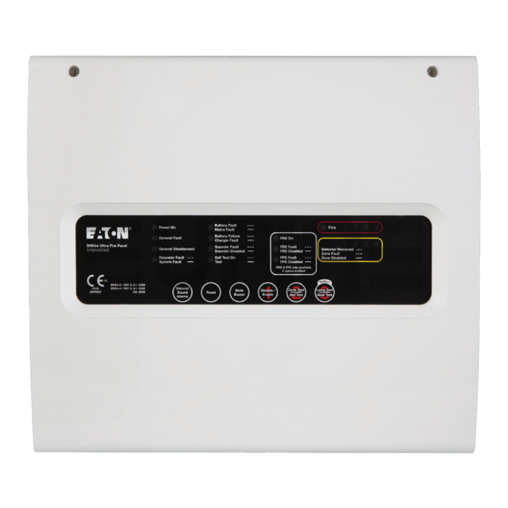
The BiWire Flexi Fire Detection & Alarm System 2.1 Control and Indication Equipment (CIE) The BiWire Flexi Fire Panel is designed as an Analogue non- The panel continuously monitors the state of each zone for addressable system. The panel enclosure is constructed Fire and Fault conditions which are only indicated on the affected zone. -
Page 7: Power Supply Equipment (Pse)
2.2 Power Supply Equipment (PSE) The PSE has been specifically designed to operate the BiWire Flexi Fire Panel and may not be substituted for any other power source. The PSE is a Switch Mode Power Supply located within the Fire Panel cabinet as shown below. -
Page 8: Eolm-3
The BiWire Flexi Fire Detection & Alarm System 2.3 EOLM-3 Each Zone on the panel that is configured for BiWire mode must have the intelligent end of line module (EOLM-3™) fitted to continually monitor each zone for the presence... -
Page 9: System Wiring
The BiWire Flexi Fire Detection & Alarm System 2.6 System Wiring BiWire Zone Conventional Zone Intrinsically Safe Zone Conventional Sounder Circuit Intrinsically Safe Sounder Circuit Figure 5: System Wiring Diagram For zones configured in BiWire mode the zone can be wired... -
Page 10: Status Indications
The BiWire Flexi Fire Detection & Alarm System 2.7 Status Indications Figure 6: Visual Indications ON (---------) Indicator lit Indicator unlit SLOW ( - - - - ) Indicator slow flashing, buzzer slow pulsing FAST ( - - - - - ) -
Page 11: Control Panel Inputs And Outputs
The BiWire Flexi Fire Detection & Alarm System 2.8 Control Panel Inputs and Outputs Figure 7: Panel Wiring Diagram Auxiliary Output The Auxiliary Output is a 30V DC output provided at the panel to power ancillary equipment. The current consumed by this output must be considered when calculating battery standby times. -
Page 12: Fire Relay
The Interlink Relay in conjunction with a non-latching zone can be used to link two BiWire Flexi fire panels together (Figure 12) or to link a BiWire Flexi to a BiWire Ultra panel. It is recommended to use a non-latching zone in the BiWire mode and fit the EOLM-3 at the interlink relay of each panel. -
Page 13: Detector Zone Inputs
The BiWire Flexi Fire Detection & Alarm System Detector Zone Inputs Repeater I/O Each zone is configured by default to BiWire mode and is Each repeater has its own mains supply and standby battery. provided with an EOLM-3 fitted inside panel. -
Page 14: Installation Instructions
HAVE FULLY READ AND UNDERSTOOD THE OPERATION AS DESCRIBED WITHIN THIS MANUAL, FAILURE TO DO SO MAY RESULT IN DAMAGE TO THE EQUIPMENT AND COULD INVALIDATE YOUR WARRANTY. Figure 12: System Cabling March 2016 www.eaton.com EATON BiWire Flexi Installation Manual (PR215-216-520-03 15-03-16, PINSTFLEXIINST) www.acornfiresecurity.com... -
Page 15: Panel Installation
PCB up, to the right and forwards as shown in Figure 16. Figure 14: Removing the PCB Shelf Figure 15: Disconnecting the PSE Figure 16: Removing the PSE March 2016 www.eaton.com EATON BiWire Flexi Installation Manual (PR215-216-520-03 15-03-16, PINSTFLEXIINST) www.acornfiresecurity.com... - Page 16 Figure 14 and Figure 15. • Fit the door back onto the back box by following the reverse instructions in Figure 13 Figure 18: Securing the Panel to the Wall March 2016 www.eaton.com EATON BiWire Flexi Installation Manual (PR215-216-520-03 15-03-16, PINSTFLEXIINST) www.acornfiresecurity.com...
-
Page 17: Connecting The Mains Supply
Do not connect the plastic socket end of the battery cable to the PSE until all installation actions in this guide have been completed and the system is ready for testing. Figure 20: Battery Cover Removal March 2016 www.eaton.com EATON BiWire Flexi Installation Manual (PR215-216-520-03 15-03-16, PINSTFLEXIINST) www.acornfiresecurity.com... -
Page 18: Connecting The Zone Cables
OR FAULT INDICATION ON THE PANEL WILL NOT MATCH THE ZONE MAP OF THE SITE, AND WILL NOT BE COMPLIANT TO BS5839. Sounders Zones Figure 22: Panel Wiring Diagram March 2016 www.eaton.com EATON BiWire Flexi Installation Manual (PR215-216-520-03 15-03-16, PINSTFLEXIINST) www.acornfiresecurity.com... -
Page 19: Connecting The Input/Output Cables
NO OTHER DEVICES ARE TO BE CONNECTED TO A ZONE CONFIGURED FOR INTERLINKING. WARNING THE UNLATCHING SETTING IS NOT TO BE USED WITH DETECTION ZONES AS THIS WILL MAKE THE PANEL NON-COMPLIANT. March 2016 www.eaton.com EATON BiWire Flexi Installation Manual (PR215-216-520-03 15-03-16, PINSTFLEXIINST) www.acornfiresecurity.com... -
Page 20: Option Board Installation
These outputs are not monitored so there is no need for a 6K8 termination resistor. Change the jumpers on the zonal relays to get them to operate in either normally open or normally closed during a fire alarm condition. March 2016 www.eaton.com EATON BiWire Flexi Installation Manual (PR215-216-520-03 15-03-16, PINSTFLEXIINST) www.acornfiresecurity.com... -
Page 21: Panel Configuration
SW3.7 = ON SW5.7 = ON SW5.7 = OFF SW5.7 = OFF SW3.8 = N/A SW3.8 = OFF SW3.8 = ON SW5.8 = ON SW5.8 = OFF SW5.8 = OFF March 2016 www.eaton.com EATON BiWire Flexi Installation Manual (PR215-216-520-03 15-03-16, PINSTFLEXIINST) www.acornfiresecurity.com... -
Page 22: Detector Fitting
FAILURE TO FOLLOW THE INSTRUCTIONS ABOVE WILL RESULT IN THE PANEL ENTERING A FULL ALARM CONDITION WHICH WILL EVACUATE THE SITE AND ACTIVATE ANY OTHER EQUIPMENT ATTACHED TO THE FIRE ALARM SYSTEM. March 2016 www.eaton.com EATON BiWire Flexi Installation Manual (PR215-216-520-03 15-03-16, PINSTFLEXIINST) www.acornfiresecurity.com... -
Page 23: Installation Testing
• Take the zone out of Zone Test mode (see section 6.7). Reset the system to clear all fire indications. March 2016 www.eaton.com EATON BiWire Flexi Installation Manual (PR215-216-520-03 15-03-16, PINSTFLEXIINST) www.acornfiresecurity.com... -
Page 24: Fire Outputs & Battery Check
• All fire alarm devices are sounding. Perform a soft reset and then check that the panel and interlinked panel have returned to the normal condition with mains fault. March 2016 www.eaton.com EATON BiWire Flexi Installation Manual (PR215-216-520-03 15-03-16, PINSTFLEXIINST) www.acornfiresecurity.com... -
Page 25: Commissioning & System Handover
4. Commissioning & System Handover 4.1 Commissioning The walk test feature (see 6.10 for more details) has been provided to facilitate the commissioning of the BiWire Flexi system. The commissioning of the system should be conducted in accordance to BS5839 part 1 Annex H. -
Page 26: Maintenance
• Carry out the weekly test and record the results in the log book. • Carry out the Quarterly testing. • Test ALL fire detection devices and manual call points. March 2016 www.eaton.com EATON BiWire Flexi Installation Manual (PR215-216-520-03 15-03-16, PINSTFLEXIINST) www.acornfiresecurity.com... -
Page 27: Operating Instructions
Note: When performing a reset, any test cases will be cleared March 2016 www.eaton.com EATON BiWire Flexi Installation Manual (PR215-216-520-03 15-03-16, PINSTFLEXIINST) www.acornfiresecurity.com... -
Page 28: Mute Buzzer
1 (5 times) + 3 1 (9 times) + 3 FPE (if fitted) 1 (4 times) + 3 1 (6 times) + 3 1 (10 times) + 3 March 2016 www.eaton.com EATON BiWire Flexi Installation Manual (PR215-216-520-03 15-03-16, PINSTFLEXIINST) www.acornfiresecurity.com... -
Page 29: Individual Zone Test
• Each indicator on the front of the panel will turn on in turn and then turn off in turn (excluding the Power On indicator). • This function will immediately exit back to Access Level 1. March 2016 www.eaton.com EATON BiWire Flexi Installation Manual (PR215-216-520-03 15-03-16, PINSTFLEXIINST) www.acornfiresecurity.com... -
Page 30: Self-Test Mode
• If no fire detection device or manual call point is triggered within 10 minutes of the walk test being started, the test mode will timeout and return back to access level 1/normal condition. March 2016 www.eaton.com EATON BiWire Flexi Installation Manual (PR215-216-520-03 15-03-16, PINSTFLEXIINST) www.acornfiresecurity.com... -
Page 31: Technical Specifications
Volt-Free, Single Pole Double Throw Fault Relay Rating 30V DC, 1A Fuse 500mA PTC Type Volt-Free, Single Pole Double Throw Interlink Relay Rating 30V DC, 1A Fuse 500mA PTC March 2016 www.eaton.com EATON BiWire Flexi Installation Manual (PR215-216-520-03 15-03-16, PINSTFLEXIINST) www.acornfiresecurity.com... - Page 32 Cable Type Cable type 2 core 1.5mm, 2 screened fire rated cable, 500m (max per zone) COMPLIANCE Compliance to standards EN54 Part 2 CIE & Part 4 PSE, BS5839-pt1 March 2016 www.eaton.com EATON BiWire Flexi Installation Manual (PR215-216-520-03 15-03-16, PINSTFLEXIINST) www.acornfiresecurity.com...
-
Page 33: Pse Specification
EFBW4ZONE-FLEXI EFBW8ZONE-FLEXI POWER SPECIFICATION Operating Voltage 18.75-30.7V Nominal Current 1.7mA 7.4 EOLM-1 Specification BiWire Flexi Fire Panel EFBW2ZONE-FLEXI EFBW4ZONE-FLEXI EFBW8ZONE-FLEXI POWER SPECIFICATION Operating Voltage 18.75-30.7V Nominal Current 1.4mA March 2016 www.eaton.com EATON BiWire Flexi Installation Manual (PR215-216-520-03 15-03-16, PINSTFLEXIINST) www.acornfiresecurity.com... -
Page 34: Option Board Specification
1-1.5mm²; Cable Type - Firetuf FT120 /FP200. Cable Size Manufacturer Draka UK to Standard - suitable for all applications described in BS 5839-1:2013, 6, 8 & 9 and BS5266-1. March 2016 www.eaton.com EATON BiWire Flexi Installation Manual (PR215-216-520-03 15-03-16, PINSTFLEXIINST) www.acornfiresecurity.com... -
Page 35: Manufacturers Contact Details
Durability Of Operational Reliability, Pass Durability Of Operational Reliability, Pass Electrical Stability Electrical Stability Durability Of Operational Reliability, Pass Durability Of Operational Reliability, Pass Humidity Resistance Humidity Resistance March 2016 www.eaton.com EATON BiWire Flexi Installation Manual (PR215-216-520-03 15-03-16, PINSTFLEXIINST) www.acornfiresecurity.com... - Page 36 Eaton is a registered trademark. © 2016 Eaton All Rights Reserved All other trademarks are property Printed in UK of their respective owners. March 2016 www.acornfiresecurity.com...
Need help?
Do you have a question about the BiWire Flexi and is the answer not in the manual?
Questions and answers