Sign In
Upload
Download
Table of Contents
Contents
Add to my manuals
Delete from my manuals
Share
URL of this page:
HTML Link:
Bookmark this page
Add
Manual will be automatically added to "My Manuals"
Print this page
×
Bookmark added
×
Added to my manuals
Manuals
Brands
Ayrton Manuals
Lighting Equipment
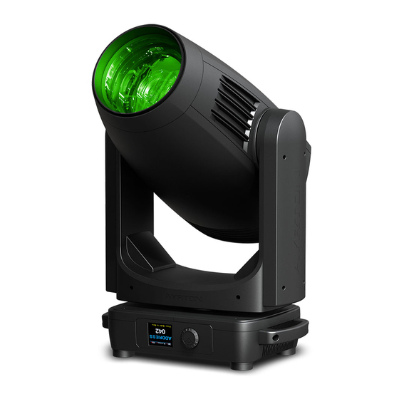
eurus s
User manual
Ayrton eurus s User Manual
Hide thumbs
1
Table Of Contents
2
3
4
5
6
7
8
9
10
11
12
13
14
15
16
17
18
19
20
21
22
23
24
25
26
27
28
29
30
31
32
33
34
35
36
37
38
39
40
41
42
43
44
45
46
47
48
page
of
48
Go
/
48
Contents
Table of Contents
Bookmarks
Table of Contents
Table of Contents
Safety Instructions
Features
Fixture Overview
Dimensional Drawings
Installation Instructions
DMX-512 Control Connection
DMX-512 Connection with DMX Terminator
Device DMX Start Address Selection
Operting Instructions of the Internal DMX Wireless System
Display
DMX Protocol
Error Messages
Cleaning and Maintenance
Advertisement
Quick Links
1
Features
2
Fixture Overview
3
Installation Instructions
4
DMX Protocol
5
Error Messages
6
Cleaning and Maintenance
Download this manual
User Manual
KEEP THIS MANUAL FOR FUTURE NEEDS
Table of
Contents
Previous
Page
Next
Page
1
2
3
4
5
Advertisement
Table of Contents
Need help?
Do you have a question about the eurus s and is the answer not in the manual?
Ask a question
Questions and answers
Related Manuals for Ayrton eurus s
Lighting Equipment AYRTON easyColor Instruction Manual
(16 pages)
Lighting Equipment Ayrton eurus tc User Manual
(48 pages)
Lighting Equipment Ayrton icecolor 1000 User Manual
Led color changer (28 pages)
Lighting Equipment Ayrton icecolor 250 User Manual
Led color changer (28 pages)
Lighting Equipment Ayrton madesign User Manual
Led color changer (18 pages)
Lighting Equipment AYRTON WILDSUN500 User Manual
(40 pages)
Lighting Equipment Ayrton magicpanelR User Manual
(31 pages)
Lighting Equipment Ayrton wild sun 200 User Manual
(34 pages)
Lighting Equipment Ayrton Diablo S Manual
(41 pages)
Lighting Equipment Ayrton Lynx Control Manual
(9 pages)
Lighting Equipment Ayrton RIVALE PROFILE User Manual
(20 pages)
Lighting Equipment Ayrton VELOCE PROFILE ULTIMATE IP65 6 Series User Manual
(20 pages)
Lighting Equipment Ayrton STRADALE PROFILE User Manual
(16 pages)
Lighting Equipment Ayrton huracan WASH User Manual
(12 pages)
Lighting Equipment Ayrton Levante S Manual
(36 pages)
Lighting Equipment Ayrton magicblade FX User Manual
Multi-sources creative series (10 pages)
This manual is also suitable for:
Eurus tc
Table of Contents
Print
Rename the bookmark
Delete bookmark?
Delete from my manuals?
Login
Sign In
OR
Sign in with Facebook
Sign in with Google
Upload manual
Upload from disk
Upload from URL


Need help?
Do you have a question about the eurus s and is the answer not in the manual?
Questions and answers