
Related Manuals for Ayrton magicpanelR


Summary of Contents for Ayrton magicpanelR
- Page 1 USER MANUAL KEEP THIS MANUAL FOR FUTURE NEEDS AYRTON – Le Parc de l’Evénement – 1, Allée d’Effiat – 91160 LONGJUMEAU – France www.ayrton.eu...
-
Page 2: Table Of Contents
Contents 1. Features ................................2 2. Fixture Overview .............................. 3 3. SAFETY INSTRUCTIONS ..........................3 3.1) Important safety warns ........................3 3.2) GENERAL GUIDELINES ........................4 4. INSTALLATION INSTRUCTIONS ......................5 4.1) Mounting the device ..........................5 5. DMX-512 control connection .......................... 8 6. -
Page 3: Features
Thank you for your patronage. We are confident that our excellent products and service can satisfy you. For your own safety, please read this user manual carefully before installing the device. In order to install , operate, and maintain the lighting safety and correctly. We suggest that the installation and operation should be done by the verified technician and follow the instruction strictly. -
Page 4: Fixture Overview
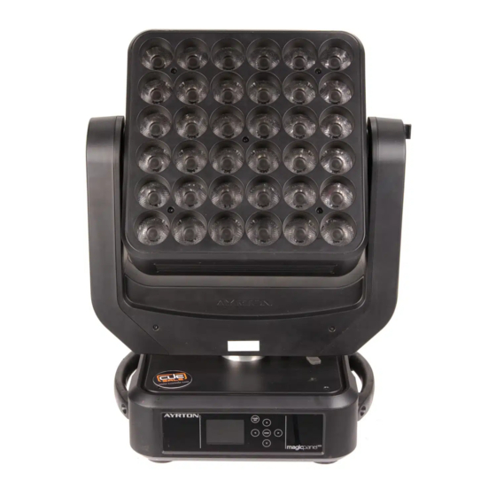
2. Fixture Overview 1: Lens 2: Display 3: Left-button 4: Down-button 5: ENTER-button 6: Right-button 7: Mode/Esc-button 8: Up-button 9: Handle 10: Antenna – Wireless DMX 11: 5-Pin DMX out 12: 5-Pin DMX in 13: RJ45 out 14: RJ45 in 15: Fuse 16: Power in 17: Power out... -
Page 5: General Guidelines
This device falls under protection-class I. Therefore it is essential that the device be earthed. If protection screen,lens or ultraviolet screen in the fixture is apparently damaged or is damaged to exceed their own effective degree, such as cracked and gashed, it must be replaced. The electric connection must carry out by qualified person. -
Page 6: Installation Instructions
If you use the quick lock cam in hanging up the fixture, please make sure the quick lock fasteners turned in the quick lock holes correctly. Operate the device only after having familiarized with its functions. Do not permit operation by persons not qualified for operating the device. - Page 7 Before mounting make sure that the installation area can hold a minimum point load of 10 times the device’s weight. Connect the fixture to the mains with the power plug. Installation via the Omega holders a) Fixed the clamp on the bracket by tighten up the M12 screw on the bracket to the Ф13 hole in the middle of the bracket.
- Page 8 Dimensional Drawings:...
-
Page 9: Dmx-512 Control Connection
Layout Drawings: Mounting points Be sure this fixture is kept at least 0.5m away from any flammable materials (decoration etc.). Always use and install the supplied safety cable as a safety measure to prevent accidental damage and/or injury in the event the clamp fails. Overhead mounting requires extensive experience, including amongst others calculating working load limits, a fine knowledge of the installation material being used, and periodic safety inspection of all installation material and the fixture. -
Page 10: Dmx-512 Connection With Dmx Terminator
Address 41 Address 21 Address 1 6. DMX-512 connection with DMX terminator For installations where the DMX cable has to run a long distance or is in an electrically noisy environment, such as in a discotheque, it is recommended to use a DMX terminator. This helps in preventing corruption of the digital control signal by electrical noise. -
Page 11: Operting Instructions Of The Internal Dmx Wireless System
8. Operting instructions of the internal DMX wireless system 1. Equipments: DMX 512 controller, wireless transmitter, and the fixtures with wireless receiver. 2. Message from the LED indicator: 1) Rapid flashing red/Green: logging in to a transmitter 2) Slow flashing Red/Green: Logged on a transmitter and the DMX line is idle (No DMX is connected to transmitter). -
Page 12: Control Board
connection with all the fixtures. b) All the red/green LEDs on the receiver fixtures will turn to Solid red to indicate that the receivers are unassigned and removed from the transmitter ( T1); c) Press and hold the configuration button on the T2 less then less than 3 second , the fixtures will connect with the T2 PS: 1. - Page 13 Service PIN Password=XXX Service Password“=050” RDM PID Xxxxxx RDM PID Code Set Ip xxx.xxx.xxx.xxx KlingNet Device ID Service PIN Set Device ID IP Addr Set LED BIN LED BIN LED BIN Change To BIN LED BIN LED BIN Auto Fans Control Head Control High Head Fans Speed Mode Select...
-
Page 14: Address
Program 1 Program Test Testing program Edit Prog. Step 01=SCxxx Program in loop Program 10 Step 64=SCxxx Save and exit Pan,Tilt,…… Edit Scene 001 --Fade Time-- Save and automatically return Edit Scenes ~ Edit Scene 250 --Secne Time-- manual scenes edit Input By Outside Scenes Input XX~XX... - Page 15 4. The display show “Hold” ,Press <Up/Down>, the display will show “Close”, “Auto”, “Music”. 5. Press <ENTER> to confirm or press <MODE/ESC> to return to the main menu. Pan Reverse With this function you can reverse the Pan-movement. 1. Access the main menu. 2.
-
Page 16: Service Pin
4. The display show “Speed 1”,Press <Up/Down>, the display will show “Speed 2”, “Speed 3”, “Speed 4”. 5. Press <ENTER> to confirm or press <MODE/ESC> to return to the main menu. Mic Sens. With this function, the default is 70%, you can select the desired microphone sensitivity from 0 % to 99 %. -
Page 17: Fans Control
Set Device ID 1. Access the main menu. 2. Press <Up/Down>, the display will show“Set Device ID.”. 3. Press< ENTER>, the display will show“Set Device ID”. 4. The display show“xx”. 5. Press <ENTER> to confirm or press <MODE/ESC> to return to the main menu. Set LED BIN 1. -
Page 18: Signal Select
1.Access the main menu. 2.Press <Up/Down>, the display will show“Key Lock”. 3.Press< ENTER>, the display will show“Key Lock”. 4.The display show “OFF”,Press <Up/Down>, the display will show “ON”. 5.Press <ENTER> to confirm or press <MODE/ESC> to return to the main menu. DispFlash With this function you can the entire display to be flipped by 180˚... -
Page 19: Initial Pos
9.3.9 Initial Pos. With this function, Display initial effect position. 1.Access the main menu. 2.Press <Up/Down>, the display will show“Initial Pos.”. 3.Press< ENTER>, the display will show“Initial Pos.”. 4.The display show “XXX”. 5.Press <ENTER> to confirm or press <MODE/ESC> to return to the main menu. 9.3.10 Wireless DMX From factory, this projector is prepared for wireless data transmission (W-DMX). -
Page 20: Resetdefault
With this function, you can run the internal program sound-controlled. 1. Access the main menu. 2. Tap the <Up/Down>button until“Music Ctrl.”is displayed. 3. Press <ENTER>, the display will show“Music Ctrl.”. 4. Tap the <Up/Down>button,the display will show “Master1”, ” Alone”. 5. -
Page 21: Temp. Info
2. Press <Up/Down>, the display will show “Timer PIN”. 3. Press< ENTER>, the display will show“Timer PIN”. The time password is 038. 4. Press <ENTER> to confirm or press <MODE/ESC> to return to the main menu. Clr Last Run With this function, you can clear last run time of the fixture. The display shows “ON” or “OFF”, Press “Enter”... -
Page 22: Test Channel
9.5.2 Test Channel With this function you can test each channel on its (correct) function. 1.Access the main menu. 2.Press <Up/Down>, the display will show “Test Channel”. 3.Press< ENTER>, the display will show “Test Channel”. 4.The display show “Pan Moving”frist channel, Press <Up/Down>, can choose other channel. - Page 23 The Slave unit receives data from the Master unit according to the group which the Slave unit was assigned to. If e.g. a Slave unit is set to “Slave 1” in the menu “Set to Slave”, the Master unit sends “Auto Program Part 1” to the Slave unit. If set to “Slave 2”, the Slave unit receives “Auto Program Part 2”.
-
Page 24: Instructions On Use
• Turn the encoder to select the desired scene numbers. You can program a maximum number of 250 • Press the Enter button to confirm. • Press the MODE/ESC button in order to return to the main menu. Example: Program 2 includes scenes: 10, 11, 12, 13 Program 4 includes scenes: 8, 9, 10 Program 6 includes scenes: 12, 13, 14, 15 Auto Pro Part 1 is Program 2;... - Page 25 236-255 no function Pan Motor continuous rotation no function 0-127 128-189 Forwards Pan rotation from fast to slow 190-193 No rotation 194-255 Backwards Pan rotation from slow to fast Tilt Motor continuous rotation no function 0-127 128-189 Forwards Tilt rotation from fast to slow 190-193 No rotation 194-255...
- Page 26 White LED -array 36 : 0-255 White ( 0-Black , 255-100% White ) Shutter, strobe: 0-31 Led trun off 32-63 Led turn on 64-95 Strobe effect slow to fast 96-127 Led turn on 128-159 Pulse-effect in sequences 160-191 Led turn on 192-223 Random strobe effect slow to fast 224-255...
- Page 27 95-99 Green 100-104 Blue 105-109 White 110-104 Rainbow1 115-119 Rainbow2 120-124 Rainbow3 125-255 Reserved Color Presets Dimmer: 0-255 Dimmer 0% to 100% Chase Patterns: Led trun off 0--9 10-11 Chase 1 12-13 Chase 2 14-15 Chase 3 16-17 Chase 4 18-19 Chase 5 20-21...
- Page 28 74-75 Chase 33 76-77 Chase 34 78-79 Chase 35 80-81 Chase 36 82-83 Chase 37 84-85 Chase 38 86-87 Chase 39 88-89 Chase 40 90-91 Chase 41 92-93 Chase 42 94-95 Chase 43 96-97 Chase 44 98-99 Chase 45 100-101 Chase 46 102-103 Chase 47...
- Page 29 160-161 Chase 76 162-163 Chase 77 164-165 Chase 78 166-167 Chase 79 168-169 Chase 80 170-171 Chase 81 172-173 Chase 82 174-175 Chase 83 176-177 Chase 84 178-179 Chase 85 180-181 Chase 86 182-183 Chase 87 184-185 Chase 88 186-187 Chase 89 188-189 Chase 90...
-
Page 30: Error Message
Chase Fade: 0-255 Fade Chase Reset, internal programs: 0-79 Normal 80-84 All motor reset 85-87 Scan motor reset 88-90 no function 91-93 no function 94-96 no function 97-99 no function 100-119 Internal program 1 (secne1~8 of EEPROM) 120-139 Internal program 2 (secne9~16 of EEPROM) 140-159 Internal program 3 (secne17~24 of EEPROM) 160-179... -
Page 31: Cleaning And Maintenance
12. CLEANING AND MAINTENANCE The following points have to be considered during the inspection: 1) All screws for installing the devices or parts of the device have to be tightly connected and must not be corroded. 2) There must not be any deformations on the housing, color lenses, fixations and installation spots (ceiling, suspension, trussing).
Need help?
Do you have a question about the magicpanelR and is the answer not in the manual?
Questions and answers