Table of Contents
Advertisement
Quick Links
Instructions - Parts
SST Switch
Gun
Swiveling applicator for robotic sealing applications. For professional use only.
Not approved for use in European explosive atmosphere locations.
See page 3 for model information including maximum working pressure.
Important Safety Instructions
Read all warnings and instructions in this
manual before using the equipment.
Save these instructions.
Model Numbers
25T991
25T992
25T993
™
3D
Model Numbers
25T994
25T995
25T996
3A8476A
EN
Advertisement
Table of Contents

Subscribe to Our Youtube Channel
Related Manuals for Graco 25T991


Summary of Contents for Graco 25T991
- Page 1 Not approved for use in European explosive atmosphere locations. See page 3 for model information including maximum working pressure. Important Safety Instructions Read all warnings and instructions in this manual before using the equipment. Save these instructions. Model Numbers Model Numbers 25T991 25T994 25T992 25T995 25T993 25T996...
-
Page 2: Table Of Contents
California Proposition 65 ....51 Graco Standard Warranty ....52... -
Page 3: Related Manuals
Part No. Series Pressure Material Port Options Sensor Types Configuration Type psi (MPa, bar) in degrees One Port One Material No 25T991 No Sensors 5 Pin Recirculation One Port One Material No 5 Pin and 25T992 Temperature 0, 45, 75... -
Page 4: Warnings
Warnings Warnings The following warnings are for the setup, use, grounding, maintenance, and repair of this equipment. The exclamation point symbol alerts you to a general warning and the hazard symbols refer to procedure-specific risks. When these symbols appear in the body of this manual or on warning labels, refer back to these Warnings. Product-specific hazard symbols and warnings not covered in this section may appear throughout the body of this manual where applicable. - Page 5 Warnings WARNING BURN HAZARD Equipment surfaces and fluid that is heated can become very hot during operation. To avoid severe burns: • Do not touch hot fluid or equipment. PERSONAL PROTECTIVE EQUIPMENT Wear appropriate protective equipment when in the work area to help prevent serious injury, including eye injury, hearing loss, inhalation of toxic fumes, and burns.
-
Page 6: Overview
Overview Overview Description The SST Switch 3D Gun is designed to handle most types of single component adhesives and sealants with medium to high viscosity. The SST Switch 3D Gun is a Stainless Steel, high-pressure, multi-nozzle material applicator for The solenoid valves operating the pistons for the robotic applications that require high precision and material valves are mounted externally for easy quality. -
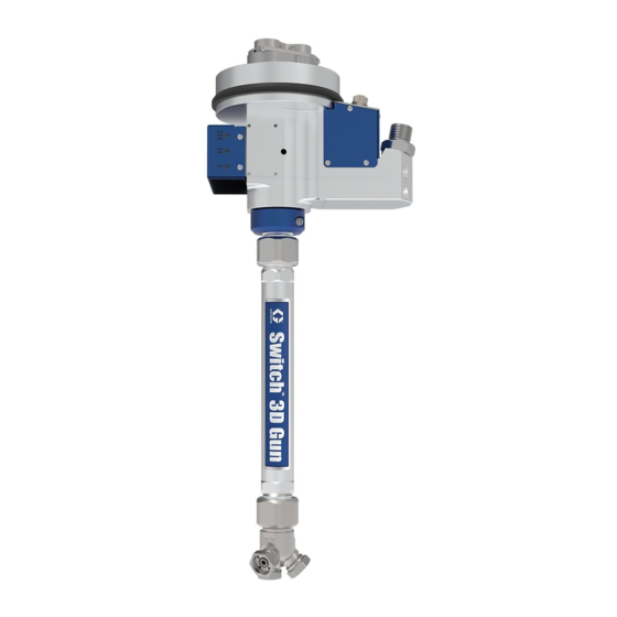
Page 7: Component Identification
Component Identification Component Identification Main Assembly Key: A. Nozzle Head and Material Tube Assembly B. Lock Ring Assembly C. Central Body Assembly D. Connection Housing E. Swivel Chamber F. Rod Shutoff Valve and Air Cylinder Assembly 3A8476A... -
Page 8: Installation
Grounding options. SST Switch 3D Gun mounting kits may be purchased separately from Graco. • 1 pc. Graco SST Switch 3D Gun with nozzle head and nozzle cap. • 1 pc. robot mounting flange. The equipment must be grounded to reduce the risk •... - Page 9 Installation Robot Mounting Flange Nozzles 1. Attach the mounting flange onto the sixth axis of the NOTE: Nozzles are not supplied with the SST Switch robot with the required bolts supplied with the SST 3D Gun and must be purchased separately to match Switch 3D Gun mounting kit.
- Page 10 Installation Customer must install air bleed valve between air supply and SST Switch 3D Gun connection. See F . 7. The material supply hose connects to the SST Switch 3D gun using a customer supplied fitting. The inlet thread is 1/2 In. BSPP. See F .
- Page 11 Installation Check for Free Movement After completing the installation of the hoses and cables, the free movement must be checked by moving the fifth axis of the robot. The hoses and cables must be able to move freely without stretching or scratching the robot arm.
-
Page 12: Operation
Operation Operation Flush the SST Switch 3D Gun Operation Overview The SST Switch 3D gun dispenses ribbons of material To avoid fire and explosion, always ground equipment onto a substrate. The height and width of the material and waste container. To avoid static sparking and bead is dependent on the nozzle selection, flow rate of injury from splashing, always flush at the lowest the material and the speed of the robot movement. -
Page 13: Maintenance
(508) inside the swivel housing, the needle years (see page 38). Both of these kits are can be ball shutoff valves (418), and needle packing (411) purchased through Graco. seals. 1. Dismount and disassemble the SST Switch 3D Gun. -
Page 14: Factors Affecting Sst Switch 3D Gun Life
Recycling and Disposal Factors Affecting SST Switch 3D Gun Life The maintenance table should be used as a guideline for the frequency of maintenance tasks. Additional factors that could affect SST Switch 3D Gun life include the following: • Material Fluid - Abrasive or fiber filled fluids are much harder on seals, shafts, and seats than non-abrasive fluids such as oil. -
Page 15: Troubleshooting
Troubleshooting Troubleshooting NOTE: Follow Pressure Relief Procedure, page 12, before checking or repairing the SST Switch 3D Gun. Problem Cause Solution Air leaks from SST Switch 3D Gun. Worn gasket. Replace gasket. Loose or worn air connections. Tighten air connections. Worn O-rings. -
Page 16: Repair
Repair Repair To help prevent serious injury from pressurized fluid, relieve pressure before cleaning, checking or servicing the equipment Removal of SST Switch 3D Gun From Robot for Repair NOTE: Clean the SST Switch 3D Gun, robot and all parts surrounding it before removing the SST Switch 3D . -
Page 17: Sst Switch 3D Gun Disassembly
Repair SST Switch 3D Gun Washer seals should be replaced with new ones before reassembly. See F . 13. Disassembly The SST Switch 3D Gun can be disassembled after being removed from the robot. See Removal of SST Switch 3D Gun From Robot for Repair. NOTICE Materials dispensed by the SST Switch 3D Gun are extremely abrasive, harden quickly and the parts must... - Page 18 Repair Remove the Pneumatic Section 1. Air cylinder assembly (401-417) and needle ball shut off valves (418) are removed together by removing the three M5 SHCS screws (408). NOTE: Be careful to not damage or bend the needle ball shut off valves (418) when extracting from housing. Various seals and gaskets that are discarded in the following procedures need to be replaced by new before reassembly.
- Page 19 Repair Nozzle Adapter Removal 1. Loosen the turnbuckle locking nut (101) by turning it counter clockwise as seen facing the main body of the SST Switch 3D Gun. The nut rotation will separate the 3 head adapter assembly (105) away from the 3D long tube assembly (103).
-
Page 20: Sst Switch 3D Gun Assembly
Repair . 20 SST Switch 3D Gun Assembly NOTE: Before assembly, It is recommended to have Yearly Service Kit, 25U328 on page No. 38. Make sure parts are thoroughly cleaned. Refer to the fastener torque settings in the Technical Specifications on page No. - Page 21 Repair 4. Apply a thin coat of lithium grease onto the outside of the next O-ring on the rotary seal (508). To prevent damage to the Rotary seal O-ring insert into the bore of the swivel housing (511) at an angle. Make sure that the O-ring does not tear against the weepage port and push the rotary seal against the material support ring (509).
- Page 22 Repair Material Tube Assembly 2. Align the four access holes in the center 3D body (301) with the M6 flathead socket screws (503) in 1. Install adapter gasket (102) into the end of the the swivel housing assembly (511). Torque center body (301).
- Page 23 Repair Air Cylinder Section Assembly 1. Install O-rings (415) then (416) onto the short bearing seal guide (413) and the long bearing seal guide (414). 2. Install one needle packing (411) seal into the short and long bearing seal guides (413 and 414) O-ring end.
- Page 24 Repair . 32 11. Apply a thin coat of lithium grease to the air gaskets (410) and insert into the 3D center body (301). 12. Insert the air cylinder assembly into the center body (301). apply medium strength threadlocker onto the M5 screws (408) and torque to 57.5 in-lb (6.5 N•m).
- Page 25 (614). See 5 Pin - No Sensor for washer (611) and install into the and install into the 25T991 and 25T994 on page 48 and 5 Pin and 8 SST single inlet adapter (602). Torque to 15 ft-lb Pin Connections for Temperature and Pressure (20.34 N•m).
- Page 26 Repair Customer supplied inlet fitting . 37 9. Install cover plates including the outer blue cover (520), two side blue covers (605) and top blue cover (606) with twelve M3 BHCS screws (514) torqued to 12 in-lb (1.35 N•m). . 38 10.
-
Page 27: Testing Before Installation
Repair Testing Before Installation If the SST Switch 3D Gun has been assembled after a major repair or maintenance operation, it is recommended to perform a function test before the SST Switch 3D Gun is returned to production. A minimum level of function test is to connect the compressed air supply and check for air leakage by opening each of the solenoid valves (613) manually. -
Page 28: Parts
Parts Parts Parts Key . 40 Key: A. Nozzle Head and Material Tube Assembly page No. 29 B. Lock Ring Assembly page No. 30 C Central 3D Body page No. 30 D.Connection Housing page No. 33 E. Swivel Chamber page No. 32 F. -
Page 29: Nozzle Head And Material Tube Assembly
Nozzle Head and Material Tube Assembly Nozzle Head and Material Tube Assembly Parts List. Model Number Ref. Part Description 25T991 25T992 25T993 25T994 25T995 25T996 15N245 NUT, turnbuckle, locking 17V839 GASKET, adapter 25U248 TUBE, 3D long, assembly 15N117 BEARING, valve shut off... -
Page 30: Lock Ring Assembly
Parts Lock Ring Assembly Lock Ring Parts List Ref. Part Description Qty. 201* 17V910 RING, lock assembly 17V817 WASHER 117026 SCREW, M5x12, SHCS * Assembly 17V910 includes parts 17V817 and 117026. Central 3D Body Central Body List Ref. Part Description Qty. -
Page 31: Needle Shutoff Valve And Air Cylinder Assembly31
Parts Needle Shutoff Valve and Air Cylinder Assembly Needle Shutoff Valve and Air Cylinder Assembly Parts List Ref. Part Description Qty. 116474 SCREW, SHCS, M4x20 17V818 COVER, cylinder 17V830 SPRING 17V826 PISTON 129647 SCREW, set, sh, cup, M3X4mm, SST 17V832 RING, guide 17V812 O-RING 108326 SCREW. -
Page 32: Swivel Chamber
Parts Swivel Chamber Central Body Assembly Parts List Ref. Part Description Qty. Ref. Part Description Qty. SCREW, M3x0.5x6, flathead, CS, 17V893 RING, dust, seal 132555 zinc 17V828 BEARING, flange 25U246 MANIFOLD, air, valve SCREW, mach, flathd, socket, 133492 FASTNER, screw, SHCS, M6x16 125609 M3x0.5x10, SS... -
Page 33: Connection Housing
Parts Connection Housing 3A8476A... - Page 34 Parts Connection Housing Parts List Quantity Per Model Number Ref. Part Description SCREW, SHCS, M5x60 125386 15N112 ADAPTER, inlet, single, SST 133162 SEAL, washer, 1/2 in. BSPP, SST 132559 SCREW, BHCS, M3x6, hex drive 15V843 COVER, side, blue 17V844 COVER, top, blue SEAL, washer, 10MM 17V808 17V795 SCREW, hex head cap, M10x12,SST...
-
Page 35: Kits And Tools
Kits and Tools Kits and Tools LASD Nozzle Assembly Kits 25U016 and 25U017 LASD Nozzle Parts List 25U016 and 25U017 Ref. Part Description 131805 SCREW, SHC, M4-0.7x10 SS 702 15N123 CLAMP 15N118 PLATE, outer, nozzle, 0.5mm,WC 15N120 PLATE.outer, nozzle, 0.4mm,WC 15N119 SPACER, nozzle, 0.5mm, WC 15N121 SPACER, nozzle, 0.4mm, WC 705 25U015 HOUSING, nozzle... -
Page 36: Lasd Nozzle Plates Assembly Kits 25U331 And 25U332
Kits and Tools Spray Stream Nozzle Kits Spray Stream Nozzle Parts List . 41 Ref. Part W in. (mm) L in. (mm) 17V669 0.012 (0.30) 0.27 (7) LASD Nozzle Plates Assembly 17V670 0.012 (0.30) 0.31 (8) Kits 25U331 and 25U332 17V671 0.012 (0.30) 0.35 (9) -
Page 37: Spray Stream Adapter Kit, 25U338
Kits and Tools Spray Stream Adapter Kit, PCF to 3D Gun Cable Kit 25U441 25U338 1001 1002 1003 PCF to 3D Gun Cable Kit Parts List Spray Stream Adapter Kit Parts List, Ref. Part Description Qty. 25U338 1001 121612 CONNECTOR, thru, M12, MXF, CABLE, GCA, M12 5P, M/F. -
Page 38: Yearly Service Kit, 25U328
Kits and Tools Yearly Service Kit, 25U328 Service Kit, 25T485 Service Kit Parts List, 25T485 Ref. Part Description Qty. 17V817 WASHER, lock ring 17V890 VALVE, solenoid 17V893 RING, dust seal NOTE: Service Kit 25t485 is provided for preventive maintenance done on the SST Switch 3D Gun once Service Kit Parts List, 25U328 every two years based on average usage. -
Page 39: Bearing And Seals Kit, 25U329
Kits and Tools Bearing and Seals Kit, 25U329 8 Pin Cable Kit, 15N265 1201 8 Pin Cable Kit Part List, 15N265 Bearing and Seals Kit Parts List, 25U329 Ref. Part Description Qty. Ref. Part Description Qty. 1201 15N265 CABLE, M12, 8 pin 17V813 PACKING, needle 15N249 BEARING, upper Material Seal Insertion/Removal... -
Page 40: Performance Charts
Performance Charts Performance Charts Pattern Width Versus Spray Stream Style Nozzle Sizes The following tests were performed using a typical PVC seam sealer. See F . 42. • 600,000 centipose • Specific gravity 0.82 The graph below shows a fixed flow rate of 9.4 cc / sec and a fixed robot speed of 300 mm / sec. -
Page 41: Nozzle Sizes
Performance Charts Material Pressure Versus Spray Stream Style Nozzle Sizes The graph below represents the pressures for each tip to achieve the width shown in the Pattern Width Versus Spray Stream Style Nozzle Sizes graph. See F . 42. Pressure data may be useful when choosing a tip size due to the pressure limitation of the metering equipment. -
Page 42: Pattern Height / Width Versus Cc/Sec For Spray Stream Style Nozzles
Performance Charts Pattern Height / Width Versus cc/sec for Spray Stream Style Nozzles Pattern Height / width Versus cc/sec 14.1 cc/sec 11.8 cc/sec 9.4 cc/sec Width 17V676 Nozzle Height . 44 Bead Pattern Spray Stream Style Nozzle Distance from the target affects the quality of the boundary layer between the sealer and the metal Correct distance for surface. -
Page 43: Pattern Thickness Versus Flow Rate And Robot Speed For 0.50 Mm Lasd Nozzle, 25U016
Performance Charts Pattern Thickness Versus flow Rate and Robot Speed for 0.50 mm LASD Nozzle, 25U016 NOTE: Typical robot speed is 300mm/sec. Bead Thickness is determined by robot speed. 0.50 mm LASD Tip 3000 cc/m in. 3000 cc/m in. 3000 cc/m in. Better Quality Lesser Quality Bead... -
Page 44: Speed For 0.40 Mm Lasd Nozzle, 25U017
Performance Charts Pattern Thickness Versus flow Rate and Robot Speed for 0.40 mm LASD Nozzle, 25U017 NOTE: Typical robot speed is 300mm/sec. Bead Thickness is determined by robot speed. 0.40 mm LASD Tip 3000 cc/m in. 3000 cc/m in. 3000 cc/m in. Better Quality Lesser Quality Bead... -
Page 45: Dimensions
124 mm 4.5 in OD 115 mm 2.50 in 63.5 mm 13 in 330.2 mm 18.64 in 1.28 in 35.2 mm 473.46 mm . 50 Side View Typical for 25T991, 25T992, 25T993, 25T994, 25T995, 25T996 With Spray Stream Nozzles 3A8476A... - Page 46 Dimensions 4 mm dia. 120° 4.05 mm dia. +/- 0.03 2 Holes on 105 mm dia. BC 40° 4.45 in dia. 113 mm M6 THRU 3 Holes EQ SP on 103 mm dia. BC . 51 Robot Mounting Flange Typical for all SST Switch 3D Guns 3A8476A...
-
Page 47: Wiring Diagrams
Wiring Diagrams Wiring Diagrams 5 Pin and 8 Pin Connector 5 Pin Cable Schematic 1 2 3 4 5 6 7 8 9 10 11 12 13 14 Pin No. Wire Color Brown White . 52 Blue Black Wire Color Grey Pink Yellow... -
Page 48: Pin - No Sensor For 25T991 And 25T994
Wiring Diagrams 5 Pin - No Sensor for 25T991 and 25T994 solenoid solenoid solenoid WIRING DIAGRAM 12, 13, 14 SOLENOID WIRING SCHEMATIC . 53 Schematic for 25T991 and 25T994 NOTE: See Electrical Components page 51 for specifications. 3A8476A... -
Page 49: Pin And 8 Pin Connections For Temperature And Pressure Sensors. Model No. 25T992, 25T993, 25T995 And 25T996
Wiring Diagrams 5 Pin and 8 Pin Connections for Temperature and Pressure Sensors. Model No. 25T992, 25T993, 25T995 and 25T996 Pressure Sensor See Note. Temperature Sensor See Note. Solenoid Solenoid Solenoid 12, 13, 14 WIRING DIAGRAM SOLENOID WIRING SCHEMATIC Pressure X-Ducer Temperature sensor SENSOR WIRING SCHEMATIC . -
Page 50: Technical Specifications
79.7 -110 in-lb 9 - 12.43 N•m 200 bar 106.2 - 135 in-lb 12 - 15.25 N•m Nozzle Angles 25T991, 25T992, 25T993 0 | 45 | 75| 25T994, 25T995, 25T996 0 | 45 | 90| Weight All Models 10.1 lb. -
Page 51: Electrical Components
Technical Specifications Electrical Components Part Number Description Electrical Rating Sensor, Temperature 100 ohm platinum rtd sensor 17V829 Transducer (350 bar, 5000 psi) 10/30 Vdc input, 0.5 to 4.5 Vdc output 15N089 Solenoid 24 Vdc: 2.88W 17V890 California Proposition 65 CALIFORNIA RESIDENTS WARNING: Cancer and reproductive harm –... -
Page 52: Graco Standard Warranty
With the exception of any special, extended, or limited warranty published by Graco, Graco will, for a period of twelve months from the date of sale, repair or replace any part of the equipment determined by Graco to be defective.
Need help?
Do you have a question about the 25T991 and is the answer not in the manual?
Questions and answers