Sony HT-MT500 Service Manual
Hide thumbs
Also See for HT-MT500:
- Operating instructions manual (143 pages) ,
- Startup manual (2 pages) ,
- Operating instructions manual (80 pages)
Table of Contents
Advertisement
SERVICE MANUAL
Ver. 1.0 2017.02
• All of the units included in the HT-MT500 (SA-
MT500/SA-WMT500/Remote control) or HT-
MT501 (SA-MT501/SA-WMT501/Remote con-
trol) are required to confi rming operation of SA-
MT500/MT501. Check in advance that you
have all of the units.
Note:
Be sure to keep your PC used for service and
checking of this unit always updated with the
latest version of your anti-virus software.
In case a virus affected unit was found during
service, contact your Service Headquarters.
COMPONENT MODEL NAME
Bar Speaker (Active Speaker System)
Subwoofer (Active Subwoofer)
• Please refer to service manual separately issued for Subwoofer.
Amplifier section
POWER OUTPUT (rated)
Front L + Front R: 25W + 25W
(at 4ohms, 1kHz, 1% THD)
POWER OUTPUT (reference)
Front L/Front R speaker blocks: 35W
(per channel at 4ohms, 1kHz)
Inputs
ANALOG IN
TV IN (OPT)
Outputs
HDMI OUT (TV (ARC))
HDMI Section
Connector
Type A (19pin)
USB section
(USB) port:
Type A (For connecting USB memory)
LAN section
LAN(100) terminal
100BASE-TX Terminal
Wireless LAN section
Communication system
IEEE 802.11 a/b/g/n
Frequency band
2.4GHz, 5GHz
9-896-356-01
2017B33-1
Sony Video & Sound Products Inc.
©
2017.02
HT-MT500/MT501
HT-MT500
HT-MT501
SA-MT500
SA-MT501
SA-WMT500
SA-WMT501
SPECIFICATIONS
BLUETOOTH section
Communication system
BLUETOOTH Specification version 4.1
Output
BLUETOOTH Specification Power
Class1
Maximum communication range
1)
Line of sight approx. 30m
Maximum number of devices to be
registered
9 devices
Frequency band
2.4 GHz band (2.4GHz - 2.4835GHz)
Modulation method
FHSS (Freq Hopping Spread Spectrum)
2)
Compatible BLUETOOTH profiles
A2DP 1.2 (Advanced Audio Distribution
Profile)
AVRCP 1.5 (Audio Video Remote
Control Profile)
3)
Supported Codecs
4)
5)
SBC
, AAC
, LDAC
Transmission range (A2DP)
20 Hz - 40,000 Hz (LDAC sampling
frequency 96kHz with 990 kbps
transmission)
20 Hz - 20,000 Hz (Sampling frequency
44.1kHz)
1)
The actual range will vary depending on
factors such as obstacles between
devices, magnetic fields around a
microwave oven, static electricity,
cordless phone use, reception
sensitivity, the operating system,
software applications, etc.
2)
BLUETOOTH standard profiles indicate
the purpose of BLUETOOTH
communication between devices.
3)
Codec: Audio signal compression and
conversion format
4)
Abbreviation for Subband Codec
5)
Abbreviation for Advanced Audio
Coding
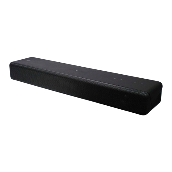
Photo: SA-MT500
Front L/Front R speaker block section
Speaker system
Full range speaker system, Acoustic
suspension
Speaker
45mm (1 13/16 in.) cone type
General
Power requirements
DC 19.5 V (using the supplied AC
adapter connected to AC 100 V - 240 V,
50 Hz/60Hz power supply)
Power consumption (using the supplied
AC adapter)
On: 30W
For details about the power
consumption during standby mode,
see "Power Consumption by the
Setting Value for Each Standby
Mode".
Dimensions* (approx.) (w/h/d)
500mm × 64mm × 108mm
(19 3/4 in x 2 5/8 in x 4 3/8 in)
(without grille frame)
500mm × 64mm × 110mm
(19 3/4 in x 2 5/8 in x 4 3/8 in)
(with grille frame)
*Not including projection portion
Mass (approx.)
2kg (4 lb 6 1/2 oz)
Compatible iPod/iPhone models
The compatible iPod/iPhone models are as
follows. Update your iPod/iPhone with the
latest software before using with the
system.
BLUETOOTH technology works with:
iPhone 7 Plus/iPhone 7/iPhone SE/
iPhone6s Plus/iPhone 6s/iPhone 6 Plus/
iPhone6/iPhone 5s/iPhone 5c/iPhone 5/
iPhone 4s
iPod touch (6th generation)/iPod touch
(5th generation)
ACTIVE SPEAKER SYSTEM
SA-MT500/MT501
AEP Model
UK Model
Wireless transmitter section
Communication system
Wireless Sound Specification version
3.0
Frequency band
5.2GHz (5.180GHz - 5.240GHz)
5.8GHz (5.736GHz - 5.814GHz)
Modulation method
DSSS
What's in the Box
• Bar Speaker (1)
• Subwoofer (1)
• Remote control (1)
• R03 (size AAA) battery (2)
• Optical digital cable (1)
• AC adapter (1)
• AC power cord (mains lead) (1)
• AC power cord (mains lead) for the
subwoofer (1)
• Speaker pad for the subwoofer (4)
• Startup Guide
• Operating Instructions
Design and specifications are subject to
change without notice.
HT-MT500/MT501
SOUND BAR
SA-MT500/MT501
Advertisement
Table of Contents


Need help?
Do you have a question about the HT-MT500 and is the answer not in the manual?
Questions and answers