Table of Contents
Advertisement
Quick Links
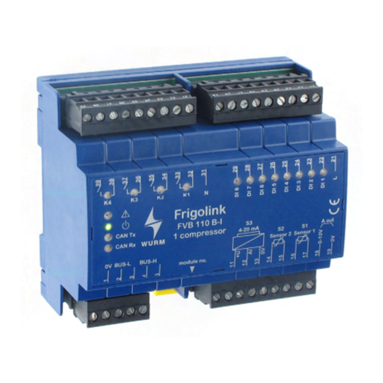
Front view
Field module for switching and monitoring 1 compressor
Features
4 relay switch outputs 230V~ for 1 compressor
230V~ inputs for operation feedback messages and detailed fault chain monitoring
Emergency program in case of CAN bus errors
No parameters to be set on the device
Control of a screw compressor by ASV001 and HVI-G3/G4
Control of a reciprocating compressor by ASV101 and HVB-G3/G4, HVI-G3/G4, HVV-G3/G4
Connection to master module via Wurm CAN field bus (F-BUS)
FVB110B_V3.30_PI_2018-01_EN
Subject to technical changes
FVB110B
Product information
Page 1 of 4
Advertisement
Table of Contents

Related Manuals for WURM Frigolink FVB110B


Summary of Contents for WURM Frigolink FVB110B
- Page 1 Control of a screw compressor by ASV001 and HVI-G3/G4 Control of a reciprocating compressor by ASV101 and HVB-G3/G4, HVI-G3/G4, HVV-G3/G4 Connection to master module via Wurm CAN field bus (F-BUS) FVB110B_V3.30_PI_2018-01_EN Subject to technical changes Page 1 of 4...
- Page 2 Wurm GmbH & Co. KG Elektronische Systeme. Keep these instructions ready to hand for quick reference and pass them on with the device if the product is sold.
- Page 3 FVB110B Product information Circuit diagram Installing WARNING! Danger to life from electric shock and/or fire! Switch off the power to the entire plant before installing! Otherwise a mains voltage and/or external voltage may still be present even if the control voltage is switched off! Always remove both power plugs (L and N)! This device is designed for top-hat rail installation.
- Page 4 FVB110B Product information Fault inputs that are not used In order to obtain correct fault information, fault inputs that are not used must be jumpered with the fault signal that is connected upstream within the alarm routing. The input "Operation" (terminal 22) is used for measuring the operating hours.
Need help?
Do you have a question about the Frigolink FVB110B and is the answer not in the manual?
Questions and answers