
Subscribe to Our Youtube Channel
Related Manuals for Extreme Networks ExtremeRouting SLX 9740

Summary of Contents for Extreme Networks ExtremeRouting SLX 9740
- Page 1 ExtremeRouting SLX 9740 Hardware Installation Guide 9036696-01 Rev. AA October 2020...
- Page 2 Copyright © 2020 Extreme Networks, Inc. All rights reserved. Legal Notice Extreme Networks, Inc. reserves the right to make changes in specifications and other information contained in this document and its website without prior notice. The reader should in all cases consult representatives of Extreme Networks to determine whether any such changes have been made.
-
Page 3: Table Of Contents
Supported hardware and software........................10 SLX 9740 Router License Option......................10 What is new in this document..........................12 Device Overview.........................13 ExtremeRouting SLX 9740 Product Introduction..................13 Hardware features..............................13 Device management options..........................15 Power Supplies........................16 Precautions specific to power supplies......................16 Power Supplies for Use with Your Device.......................16... - Page 4 Removing and Replacing Components ................. 68 Replacing Internal Power Supplies........................68 Removing the Device from the Rack....................... 68 Fan Assemblies........................72 Fan assemby overview............................72 Precautions specific to fan assemblies......................73 Identifying the airflow direction..........................73 Replacing Fan Modules............................74 ExtremeRouting SLX 9740 Hardware Installation Guide...
- Page 5 Table of Contents Changing Airflow Direction...........................75 ExtremeRouting SLX 9740 Technical Specifications........... 78 SLX 9740 Software Specifications........................78 Weights and Physical Dimensions........................80 Acoustic Specifications ............................82 Power Options................................82 Mean Time Between Failures (MTBF)......................83 CPU, Memory................................83 Standards..................................84 Environmental Data..............................86 1600 W Power Supplies Technical Specifications..................86 Power Cord Requirements for AC-Powered Switches and AC Power Supplies......88...
-
Page 6: Preface
ExtremeSwitching switches or SLX routers, the product is referred to as the switch or the router. Table 1: Notes and warnings Icon Notice type Alerts you to... Helpful tips and notices for using the product. Note Useful information or instructions. Important Important features or instructions. ExtremeRouting SLX 9740 Hardware Installation Guide... - Page 7 Repeat the previous element, for example, member[member...]. In command examples, the backslash indicates a “soft” line break. When a backslash separates two lines of a command input, enter the entire command at the prompt without the backslash. ExtremeRouting SLX 9740 Hardware Installation Guide...
-
Page 8: Documentation And Training
Extreme Optics Compatibility Other resources such as white papers, data sheets, and case studies Extreme Networks offers product training courses, both online and in person, as well as specialized certifications. For details, visit www.extremenetworks.com/education/. Getting Help If you require assistance, contact Extreme Networks using one of the following methods: Extreme Portal Search the GTAC (Global Technical Assistance Center) knowledge base;... -
Page 9: Providing Feedback
4. Select Submit. Providing Feedback The Information Development team at Extreme Networks has made every effort to ensure the accuracy and completeness of this document. We are always striving to improve our documentation and help you work better, so we want to hear from you. We welcome all feedback, but we especially want to know about: •... -
Page 10: About This Document
Supported hardware and software on page 10 What is new in this document on page 12 Supported hardware and software The following table describes the ExtremeRouting SLX 9740 models: Table 4: SLX 9740 Switch Router Models Part number Description Introduced OS... - Page 11 Table 8: Supported SLX 9740 Router Rack Mount Kit Part number Description XN-2P-RKMT299 2 post Rail kit for SLX9740-40C XN-2P-RKMT300 2 Post Rail Kit for SLX9740-80C XN-4P-RKMT301 4 Post Rail Kit for SLX9740-80C XN-4P-RKMT302 4 Post Rail Kit for SLX9740-40C ExtremeRouting SLX 9740 Hardware Installation Guide...
-
Page 12: What Is New In This Document
SLX 9740-40C and SLX 9740-80C) For information about licensing option for SLX-OS support for SLX 9740 switch routers, reference Extreme SLX-OS Software Licensing Guide. What is new in this document This is a new document. ExtremeRouting SLX 9740 Hardware Installation Guide... -
Page 13: Device Overview
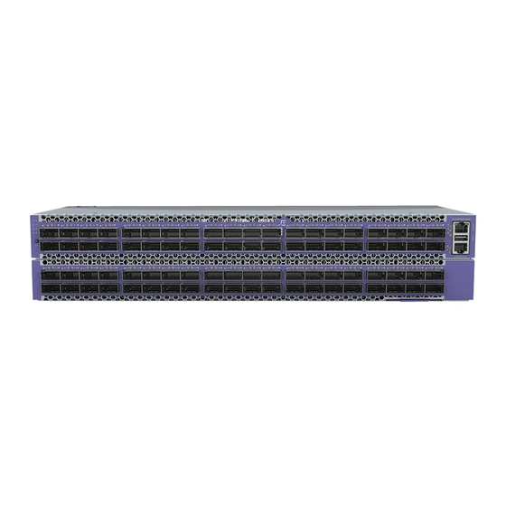
This platform provides carrier-class advanced features that leverage proven Extreme Networks routing, MPLS, Carrier Ethernet, and VXLAN overlay technology, deployed in the most demanding service providers, internet exchange points (IXPs) and large enterprise data centers. - Page 14 Figure 1: SLX9740-40C Front Panel 1 = LEDs 4 = USB port 2 = 100GE/40GE QSFP28 ports 5 = Console port 3 = Management port Figure 2: SLX9740-40C Rear Panel 1 = Power supplies 2 = Fan modules ExtremeRouting SLX 9740 Hardware Installation Guide...
-
Page 15: Device Management Options
Ethernet or serial Extreme SLX-OS Management (CLI) connection Configuration Guide REST or NETCONF/YANG Ethernet connection Yes Extreme SLX-OS Management APIs. Configuration Guide Standard SNMP applications Ethernet or serial Extreme SLX-OS Management connection Configuration Guide ExtremeRouting SLX 9740 Hardware Installation Guide... -
Page 16: Power Supplies
You can remove one power supply without interrupting the device's operation. For more information, see the following topics. • 1600 W AC Power Supplies on page 17 ExtremeRouting SLX 9740 Hardware Installation Guide... -
Page 17: 1600 W Ac Power Supplies
Note AC power input cords are not provided with AC power supplies. You can order an appropriate cord from Extreme Networks or from your local supplier. The power cord must meet the requirements listed in Power Cord Requirements for AC-Powered Switches and AC Power... -
Page 18: Preparing For The Installation
29 Preparing for the Installation Before you install your Extreme Networks equipment, careful planning can help ensure that it is used effectively and help prepare you for future growth. Only qualified service personnel should install, maintain, or remove a device, chassis, or its components. -
Page 19: Safety Precautions
Ensure that the airflow direction of the power supply unit matches that of the installed fan tray. The power supplies and fan trays are clearly labeled with either a green arrow with an "E", or an orange arrow with an "I." ExtremeRouting SLX 9740 Hardware Installation Guide... -
Page 20: Esd Precautions
The mark is your assurance that the power cord can be used safely with the device. Warning Disconnect the power cord from all power sources to completely remove power from the device. ExtremeRouting SLX 9740 Hardware Installation Guide... -
Page 21: Lifting Precautions
These handles were not designed to support the weight of the chassis. Laser precautions Warning All fiber-optic interfaces use Class 1 lasers. Warning Laser Radiation. Do Not View Directly with Optical Instruments. Class 1M Laser Products. ExtremeRouting SLX 9740 Hardware Installation Guide... -
Page 22: Shipping Carton Contents
Preparing for the Installation Warning Use only optical transceivers that are qualified by Extreme Networks, Inc. and comply with the FDA Class 1 radiation performance requirements defined in 21 CFR Subchapter I, and with IEC 60825 and EN60825. Optical products that do not comply with these standards might emit light that is hazardous to the eyes. -
Page 23: Setting Up The Wiring Closet
Prevent unauthorized access to wiring closets by providing door locks. Install the equipment in a secured, enclosed, and restricted access location, ensuring that only qualified service personnel have access to the equipment. • Provide adequate overhead lighting for easy maintenance. ExtremeRouting SLX 9740 Hardware Installation Guide... -
Page 24: Controlling The Temperature
Alternately, you can restart the system immediately by removing and then restoring all line power to the system. Safeguards are built into all Extreme Networks switches and power supply units to minimize the risk of fire. Controlling the Humidity Level To maximize equipment life, keep operating humidity between 50% and 70% relative humidity (non- condensing) during typical operation. -
Page 25: Protecting Your System From Esd (Electrostatic Discharge)
CAD weld appropriate wire terminals to building I-beams or earth ground rods. • For a DC-powered switch, use a minimum 14 AWG stranded copper wire for grounding. AC-powered switches do not need separate chassis grounding. ExtremeRouting SLX 9740 Hardware Installation Guide... -
Page 26: Providing Adequate Space For The Rack
Extra room on each side is optional. Warning Extreme Networks switches do not have a switch for turning power to the unit on and off. For systems using an AC power supply, power to the switch is disconnected by removing the wall plug from the electrical outlet. -
Page 27: Meeting Power Requirements
ExtremeRouting SLX 9740 Technical Specifications on page 78. Requirements for Power Cords Most ExtremeSwitching devices do not ship with power cords. Visit www.extremenetworks.com/ product/powercords/ for information on selecting and purchasing the correct power cords for use with ExtremeRouting SLX 9740 Hardware Installation Guide... -
Page 28: Ups (Uninterruptible Power Supply) Requirements
UPS (Uninterruptible Power Supply) Requirements Preparing for the Installation specific Extreme Networks equipment. The web page provides specifications for power cords in each country so that you can purchase cords locally. UPS (Uninterruptible Power Supply) Requirements A UPS (uninterruptible power supply) is a device that sits between a power supply (such as a wall outlet) and a device (such as a switch) to prevent outages, sags, surges, and bad harmonics from adversely affecting the performance of the device. -
Page 29: Following Applicable Industry Standards
UPS transfer time. UPS transition times vary between UPS models and implementations, but shorter transition times are preferred. For Extreme Networks stacking products, we recommend a UPS transition time of 20 milliseconds or less to ensure optimum performance and minimize service interruptions. -
Page 30: Installing Your Device
Connecting Network Interface Cables on page 52 Installing Your Device Before you attempt to install or remove an Extreme Networks switch or router, read the precautions in Safety Considerations for Installing Switches on page 31. Extreme Networks switch routers fit into standard 19-inch equipment racks. -
Page 31: Safety Considerations For Installing Switches
18 and ensure that you have the appropriate people and tools on hand. Installing Extreme Networks switch routers is easiest when there are two people to maneuver the device and attach mounting hardware. Provide enough space in front of and behind the switch so that you can service it easily. Allow a minimum of 122 cm (48 in) in front of the rack and 76 cm (30 in) behind the rack. -
Page 32: Attaching The Switch To A Rack
38 Note • When you install Extreme Networks switches, we recommend that you have two people to maneuver the switch and the mounting hardware. • Take care to load the rack so that it is not top-heavy. Start installing equipment at the bottom and work up. - Page 33 Figure 7: Remove inner rail 3. Align the hooks on the device with the holes in the inner rail, and then slide the inner rail backward until it is locked in place. ExtremeRouting SLX 9740 Hardware Installation Guide...
- Page 34 Figure 9: Outer rail installation - rear 5. For the front brackets, pull the latch and install the outer rail by aligning the hooks with the front rack holes. Then release the latch to lock the hooks into place. ExtremeRouting SLX 9740 Hardware Installation Guide...
- Page 35 Figure 10: Install outer rail 7. Slide the inner rails on the device into the middle rails and push the device all the way to the rear of the rack. Figure 11: Securing rails - front ExtremeRouting SLX 9740 Hardware Installation Guide...
- Page 36 8. Screw the mounting ear thumbscrews into the rack rails to hand tightness. The completed assembly is shown in the Figure Completed Installation: Switch Router in 4-Post Rack. Figure 13: Completed Installation: Switch Router in 4-Post Rack ExtremeRouting SLX 9740 Hardware Installation Guide...
- Page 37 52 . If your device does not have an installed power supply, install one or two power supplies using the instructions in Installing a 1600 W Internal AC Power Supply on page 44. ExtremeRouting SLX 9740 Hardware Installation Guide...
-
Page 38: Attaching The Device To A Two-Post Rack
You can attach your switch router to a two-post rack in mid-mount configuration. Brackets for a two-post mount are not included in the box with your device. However, they can be ordered separately using part numbers XN-2P-RKMT299 or XN-2P-RKMT300. Figure 16: SLX9740-40C 2-post rack components ExtremeRouting SLX 9740 Hardware Installation Guide... - Page 39 Installing Your Device Attaching the Device to a Two-Post Rack Figure 17: SLX9740-80C 2-post rack components ExtremeRouting SLX 9740 Hardware Installation Guide...
- Page 40 Use six small mounting screws (provided) to attach the bracket to the device. 2. Attach the other short mounting bracket to the other side of the switch router housing, as you did in step 2. ExtremeRouting SLX 9740 Hardware Installation Guide...
- Page 41 If the device cannot be tilted (because other equipment is mounted directly above and below), remove one or both short mounting brackets from the device. Lift the device into position, secure the flanges (ears) on the long brackets to the rack posts, and then reattach the short brackets. ExtremeRouting SLX 9740 Hardware Installation Guide...
- Page 42 7. For SLX9740-40C, install the ground lug cables to the rack using an M6 screw and the four screws provided (grounding screws for 2-post installation shipped with the swith in separate bag). Figure 21: SLX9740-40C grounding location ExtremeRouting SLX 9740 Hardware Installation Guide...
-
Page 43: Installing Optional Components
Optical Cables Direct-attach copper and fiber cables provide connections between unpopulated QSFP+ and QSFP28 ports. To install optical cables, refer to the instructions in Extreme Networks Pluggable Transceivers Installation Guide. Breakout cables The copper breakout cables are terminated with optical connectors and are available in 1m, 3m, 5m, or greater lengths. -
Page 44: Installing Internal Power Supplies
• Installing a 1600 W Internal DC Power Supply on page 48 Installing a 1600 W Internal AC Power Supply To install a 1600 W AC power supply in a switch, follow these instructions. ExtremeRouting SLX 9740 Hardware Installation Guide... - Page 45 2. Verify that the new power supply is right side up. 3. Verify that the new power supply's airflow direction (front-to-back or back-to-front) is compatible with the other installed power supply (if any) and with the installed fan modules. ExtremeRouting SLX 9740 Hardware Installation Guide...
- Page 46 EMI levels. 6. Connect the AC power cord. a. If necessary, slide the plastic cord retainer farther away from the back of the switch. b. Connect the AC power cord to the input connector. ExtremeRouting SLX 9740 Hardware Installation Guide...
- Page 47 Always make sure that the source outlet is properly grounded before plugging the AC power cord into the AC power supply. To install a second power supply, repeat this procedure. When you are finished, follow the steps in Powering up the Device on page 52. ExtremeRouting SLX 9740 Hardware Installation Guide...
-
Page 48: Installing A 1600 W Internal Dc Power Supply
You will need three cable wires for each installed DC power supply: two input cables and a grounding cable. We recommend that each cable have differently colored insulation, as described in Required Tools and Materials for Installing a 1600 W DC Power Supply on page 48. ExtremeRouting SLX 9740 Hardware Installation Guide... - Page 49 6. To install a second power supply, repeat the procedure. When you are finished, connect the ground wire to each power supply. See Connecting the Ground Wire to a 1600 W DC Power Supply on page 50. ExtremeRouting SLX 9740 Hardware Installation Guide...
- Page 50 50. Connecting a 1600 W DC Power Supply to the Source Voltage One 1600 W DC power supply is available: model XN-DCPWR-1600W-F (front-to-back airflow). It can connect to a –48 V power source. ExtremeRouting SLX 9740 Hardware Installation Guide...
- Page 51 5. Connect the cables to the DC source voltage, using hardware appropriate to the installation site and following local and national electrical codes. Power up to the switch, following the steps in Powering up the Device on page 52. ExtremeRouting SLX 9740 Hardware Installation Guide...
-
Page 52: Powering Up The Device
An AC power cord is not included with the AC power supply. You can purchase AC power cords for use in the US and Canada from Extreme networks or from your local supplier. The cord must meet the requirements listed in... - Page 53 5. Repeat step 1 through step 5 for the remaining cables on this or other switches or I/O modules. 6. Dress and secure the cable bundle to provide appropriate strain relief and protection against bends and kinks. ExtremeRouting SLX 9740 Hardware Installation Guide...
-
Page 54: Activating And Verifying The Switch
2. Connect the RJ-45 serial cable provided with the device to the console port of the device. Shown below are the Port-side views of both SLX 9740 Switch models: Figure 27: Port-side view of the SLX 9740 Switches a. LEDs b. 100GE/40GE SQSF28 ports c. Management port ExtremeRouting SLX 9740 Hardware Installation Guide... - Page 55 When the terminal emulator application stops reporting information, press Enter. You receive the following login prompt: SLX login: 6. Follow the steps to log into the switch and initial configuration steps in Configuring the Switch for on page 56. ExtremeRouting SLX 9740 Hardware Installation Guide...
-
Page 56: Configuring The Switch For Use
Extreme SLX-OS Security Configuration Guide for the SLX 9740 device. The switch is ready for use. To configure other switch features, see Extreme SLX-OS Layer 2 Switching Configuration Guide . ExtremeRouting SLX 9740 Hardware Installation Guide... -
Page 57: Transceivers And Cables
Ethernet Optics Family Datasheet on https://cloud.kapostcontent.net/pub/a070d154-d6f1-400b- b2f0-3d039ae2f604/data-center-ethernet-optics-data-sheet and to the current SLX-OS20.2.1 for ExtremeRouting SLX 9740 Release Notes . Time and items required The installation or replacement procedure for one transceiver takes less than 5 minutes. Ensure that the following items are available: •... -
Page 58: Precautions Specific To Transceivers And Cables
All fiber-optic interfaces use Class 1 lasers. Warning Use only optical transceivers that are qualified by Extreme Networks, Inc. and comply with the FDA Class 1 radiation performance requirements defined in 21 CFR Subchapter I, and with IEC 60825 and EN60825. Optical products that do not comply with these standards might emit light that is hazardous to the eyes. -
Page 59: Installing A Qsfp28 Transceiver
Push the correctly oriented transceiver into the port until it is firmly seated and the latching mechanism clicks. Note Always use the transceiver pull tab to insert or remove the QSFP28 transceivers, as the transceiver might be hot. ExtremeRouting SLX 9740 Hardware Installation Guide... - Page 60 QSFP28 transceiver. You may damage the cable as well as the transceiver. 3. Organize cables to avoid covering LEDs and air vents so that LCs can be removed. Refer to Managing cables on page 58 for more information. ExtremeRouting SLX 9740 Hardware Installation Guide...
-
Page 61: Replacing A Qsfp28 Transceiver
The following figure uses a generic interface module. Your interface module might look different. a. Pull tab b. QSFP28 cable connector c. QSFP28 transceiver Figure 30: Replacing a QSFP28 optical transceiver into blade port ExtremeRouting SLX 9740 Hardware Installation Guide... -
Page 62: Breakout Cables
To verify operation of a transceiver, view the LEDs on the transceiver. To find the LED locations on the interface modules, refer to LED activity interpretation on page 64. After you have connected and ExtremeRouting SLX 9740 Hardware Installation Guide... - Page 63 When traffic is detected on the port, the light becomes blinking green. You can also enter the show interface status and show ip interface brief commands to verify proper transceiver operation. ExtremeRouting SLX 9740 Hardware Installation Guide...
-
Page 64: Monitoring The Device
One status bicolor status LED (green and amber) • One fan bicolor status LED (green and amber) • One PSU bicolor status LED (green and amber) The figure below shows the LEDs on the SLX 9740 switch router front panel. ExtremeRouting SLX 9740 Hardware Installation Guide... -
Page 65: Led Indicators
No Power Green Blinking Stand-By Standby output enabled with no power supply warning or fault detected Green Steady Power GOOD Main output and standby output enabled with no power supply warning or fault detected ExtremeRouting SLX 9740 Hardware Installation Guide... -
Page 66: 1600 W Ac Power Supply Leds
The following tables describe the meanings of the LEDs on the 1600 W DC power supply (part number XN-DCPWR-1600W-F). The LEDs are located on the end of the power supply unit, arranged vertically to the left of the terminal block. ExtremeRouting SLX 9740 Hardware Installation Guide... - Page 67 (Solid) No PSU fault OUT OK DC output DC output OK (Green) Good (solid) Off or DC output fail Blinking IN OK DC input DC input OK (Green) Good "IN OK" DC input fail ExtremeRouting SLX 9740 Hardware Installation Guide...
-
Page 68: Removing And Replacing Components
Attaching the Device to a Four-Post Rack on page 32 • Attaching the Device to a Two-Post Rack on page 38 1. Disconnect the device from its power source or sources. 2. Remove all cables and transceivers. ExtremeRouting SLX 9740 Hardware Installation Guide... - Page 69 Carefully slide the device out of the slider assembly and place it on a flat surface. You can leave the slider assemblies in place. If you want to remove them, continue with the next step. ExtremeRouting SLX 9740 Hardware Installation Guide...
- Page 70 On one of the slider assemblies, push the rear clamp until it separates from the rear rack post. See the diagram below - Removing the Slider Assembly: Rear Rack Post. Figure 34: Removing the Slider Assembly: Rear Rack Post ExtremeRouting SLX 9740 Hardware Installation Guide...
- Page 71 If the device cannot be tilted (because other equipment is mounted directly above and below), remove one or two mounting brackets from the device and then slide the device out. If you plan to use the device again later, we recommend storing it with the mounting brackets attached. ExtremeRouting SLX 9740 Hardware Installation Guide...
-
Page 72: Fan Assemblies
75 Fan assemby overview The ExtremeRouting SLX 9740 switch router includes four to six redundant, hot-swappable fan units. The fan assemblies in the SLX 9740 switch router chassis can be removed and replaced without special tools. The device can continue operating during the replacement. -
Page 73: Precautions Specific To Fan Assemblies
Nonport-side air exhaust ◦ Port-side air intake ◦ Front-to-back (port-side to nonport-side) ◦ airflow Part numbers ending with -F ◦ • You can check the top view of the switch to ensure proper groove alignment: ExtremeRouting SLX 9740 Hardware Installation Guide... -
Page 74: Replacing Fan Modules
3. Verify that the airflow direction on the replacement fan module matches that of the installed fan modules. Fans with front-to-back airflow have red tabs and are labeled Air Out. Fans with back-to-front airflow have blue tabs and are labeled Air In. ExtremeRouting SLX 9740 Hardware Installation Guide... -
Page 75: Changing Airflow Direction
The operating-system software cannot display the airflow direction. 1. Remove the four PSUs and four fan modules by removing the two captive retaining screws and sliding all components out of the switch: Figure 38: Remove PSUs and fan modules ExtremeRouting SLX 9740 Hardware Installation Guide... - Page 76 3. Use a flathead screwdriver to change the chassis switch. The following figure is an example of changing front-to-back airflow to back-to-front airflow: Figure 40: Front-to-back airflow chassis position Figure 41: Back-to-front airflow chassis position ExtremeRouting SLX 9740 Hardware Installation Guide...
- Page 77 Figure 42: Chassis screw back-to-front position 5. Carefully slide the PSUs and fan modules back into the switch: Figure 43: Remove PSUs and fan modules 6. Tighten the two captive retaining screws to secure the components. ExtremeRouting SLX 9740 Hardware Installation Guide...
-
Page 78: Extremerouting Slx 9740 Technical Specifications
86 Power Cord Requirements for AC-Powered Switches and AC Power Supplies on page 88 The ExtremeRouting SLX 9740 switch routers include the following models: Part number Description SLX9740-40C, 9740-40C SLX9740-40C, 9740-40C switch router with two unpopulated power supply slots and six unpopulated fan slots. - Page 79 • IEEE 802.1AB Link Layer Discovery Protocol (LLDP) • IEEE 802.3x Flow Control (Pause Frames) • IEEE 802.3ae 10 GBASE-X • IEEE 802.3 10 GBASE-T (up to 100 m using Cat6a cabling or better) • IEEE 802.3bj • IEEE 802.3by ExtremeRouting SLX 9740 Hardware Installation Guide...
-
Page 80: Weights And Physical Dimensions
SLX9740-80C fan unit, front-to-back or back-to-front 0.31 kg (0.70 lb) SLX9740-40C four-post rack mount kit (included with 2.83 kg (6.26 lb) switch) SLX9740-80C four-post rack mount kit (included with 2.95 kg (6.52 lb) switch) ExtremeRouting SLX 9740 Hardware Installation Guide... - Page 81 SLX9740-80C fan unit, front-to-back or back-to-front 0.54 kg (1.21 lb) SLX9740-40C four-post rack mount kit (included with 3.11 kg (6.87 lb) switch) SLX9740-80C four-post rack mount kit (included with 3.23 kg (7.14 lb) switch) ExtremeRouting SLX 9740 Hardware Installation Guide...
-
Page 82: Acoustic Specifications
1600 W DC power supply: Part # XN-DCPWR-1600W-F (front-to-back) DC Input: +/- 48VDC 15A Max (for PSU FSK010) for each PSU for SLX9740-40c +/- 48VDC 15A Max (for PSU FSK010) for each PSU, min. x2 for SLX9740-80C ExtremeRouting SLX 9740 Hardware Installation Guide... -
Page 83: Mean Time Between Failures (Mtbf)
CPU, Memory Table 23: CPU, Memory Both models 2.2GHz 64-bit CPU 2 x 16 Gb DDR4 SO-DIMM memory, 128 Gb SSD 16MB BIOS SPI Flash Memory 8 GB Deep Buffer for each BCM88690 MAC ASIC ExtremeRouting SLX 9740 Hardware Installation Guide... -
Page 84: Standards
FCC 47 CFR part 15 Class A (USA) ICES-003 Class A (Canada) European EMC standards EN 55032 Class A EN 55024 EN 55011 EN 61000-3-2 (Harmonics) EN 61000-3-3 (Flicker) EN 300 386 (EMC Telecommunications) 2014/30/EU EMC Directive ExtremeRouting SLX 9740 Hardware Installation Guide... - Page 85 EN/ETSI 300 019 (Environmental for Telecommunications) MEF9 and MEF14 certified for EPL, EVPL, and ELAN Table 27: IEEE 802.3 Media Access Standards IEEE 802.3ab 1000BASE-T IEEE 802.3z 1000BASE-X IEEE 802.3ae 10GBASE-X IEEE 802.3ba 40GBASE-X ExtremeRouting SLX 9740 Hardware Installation Guide...
-
Page 86: Environmental Data
Three 1600 W power supply units are available for use with SLX 9740 switch routers: • 1600W AC power supply - front-to-back airflow (part no. XN-ACPWR-1600W-F) • 1600W AC power supply - back-to-front airflow (part no. XN-ACPWR-1600W-R) • 1600W DC power supply - front-to-back airflow (part no. XN-DCPWR-1600W-F) ExtremeRouting SLX 9740 Hardware Installation Guide... - Page 87 240Vdc). Total output power not to exceed 1000W (100-120VAC). For FSG023: +12V/133A, +12Vsb/2.5A. Total output power not to exceed 1600W. Power supply input socket IEC 320 C14 Power cord input plug IEC 320 C13 ExtremeRouting SLX 9740 Hardware Installation Guide...
-
Page 88: Power Cord Requirements For Ac-Powered Switches And Ac Power Supplies
For cords up to 6 feet (2 m) long, the wire size must be 18 AWG (.75 mm ) minimum; over 6 feet, the minimum wire size is 16 AWG (1.0 mm For details about obtaining AC power cords for use in your country, refer to http:// www.extremenetworks.com/product/powercords/. ExtremeRouting SLX 9740 Hardware Installation Guide... -
Page 89: Safety And Regulatory Information
Only trained and qualified service personnel (as defined in IEC 60950-1 and AS/NZS 3260) should install, replace, or perform service to Extreme Networks switches and their components. Qualified personnel have read all related installation manuals, have the technical training and experience necessary to be aware of the hazards to which they are exposed in performing a task, and are aware of measures to minimize the danger to themselves or other persons. -
Page 90: General Safety Precautions
Make sure that your power supplies meet the site DC power or AC power requirements of all the network equipment. • Racks for Extreme Networks equipment must be permanently attached to the floor. Failure to stabilize the rack can cause the rack to tip over when the equipment is removed for servicing. •... -
Page 91: Cable Routing For Lan Systems
For the ratings and power input requirements of each power supply unit, see "Technical Specifications" or the data sheet for the power supply at www.extremenetworks.com. Warning Be sure to satisfy the requirements listed in this section when you install Extreme Networks power supplies or connect power. ExtremeRouting SLX 9740 Hardware Installation Guide... -
Page 92: Selecting Power Supply Cords
When you install DC power supplies or connect DC power: • Extreme Networks DC power supplies do not have switches for turning the unit on and off. Make sure that the DC circuit is de-energized before connecting or disconnecting the DC power cord at the DC input power socket. -
Page 93: Battery Notice
Veuillez communiquer avec l’assistance technique pour du soutien. Il y a risque d’explosion si la pile est remplacée par un type de pile incorrect. Éliminez les piles usées en conformité aux règlements locaux d'élimination des piles. ExtremeRouting SLX 9740 Hardware Installation Guide... -
Page 94: Regulatory Statements
EN 55032/EN 55024 (European Immunity Requirements) ◦ EN61000-3-2/JEIDA (European and Japanese Harmonics Spec) ◦ EN61000-3-3 China ROHS Refer to the latest revision of the China ROHS document (P/N 53‐1000428‐xx) which ships with the product. ExtremeRouting SLX 9740 Hardware Installation Guide... -
Page 95: Bsmi Statement (Taiwan)
Canadian requirements This Class A digital apparatus meets all requirements of the Canadian Interference-Causing Equipment Regulations, ICES-003 Class A. Cet appareil numérique de la classe A est conforme à la norme NMB-003 du Canada. ExtremeRouting SLX 9740 Hardware Installation Guide... -
Page 96: China Ccc Statement
China CCC statement Regulatory Statements China CCC statement Australia (RCM) Warning This equipment is compliant with Class B of CISPR 32. In a residential environment, this equipment may cause radio interference. ExtremeRouting SLX 9740 Hardware Installation Guide... -
Page 97: Federal Communications Commission (Fcc) Notice
This is a Class A product based on the standard of the VCCI Council. If this equipment is used in a domestic environment, radio interference may occur, in which case the user may be required to take corrective actions. ExtremeRouting SLX 9740 Hardware Installation Guide... -
Page 98: Japan Power Cord
Japan power cord Regulatory Statements Japan power cord English translation of above statement ATTENTION: Never use the power cord packed with your equipment for other products. ExtremeRouting SLX 9740 Hardware Installation Guide... -
Page 99: Cautions And Danger Notices
Un mensaje de precaución le alerta de situaciones que pueden resultar peligrosas para usted o causar daños en el hardware, el firmware, el software o los datos. ExtremeRouting SLX 9740 Hardware Installation Guide... -
Page 100: General Cautions
Aucune pièce du bloc de l'alimentation ou du ventilateur ne peut être réparée par l'utilisateur. PRECAUCIÓN Si se desmonta cualquier pieza del módulo de fuente de alimentación y ventiladores, la garantía y las certificaciones normativas quedan anuladas. En el interior del ExtremeRouting SLX 9740 Hardware Installation Guide... - Page 101 PRECAUCIÓN Para evitar que se dañe el puerto serie, mantenga la cubierta colocada sobre el puerto cuando no lo utilice. Caution Never leave tools inside the chassis. Lassen Sie keine Werkzeuge im Chassis zurück. ExtremeRouting SLX 9740 Hardware Installation Guide...
- Page 102 Au cours de cette procédure, l'appareil doit être éteint et déconnecté du réseau. GARDE PRECAUCIÓN El dispositivo debe estar apagado y desconectado del fabric durante este procedimiento. ExtremeRouting SLX 9740 Hardware Installation Guide Caution All devices with DC power supplies are intended for installation in restricted access areas only.
-
Page 103: Danger Notices
Una advertencia de peligro indica condiciones o situaciones que pueden resultar potencialmente letales o extremadamente peligrosas. También habrá etiquetas de seguridad pegadas directamente sobre los productos para advertir de estas condiciones o situaciones. ExtremeRouting SLX 9740 Hardware Installation Guide... -
Page 104: General Dangers
Jetez/recyclez les batteries conformément aux normes locales. PELIGRO Las baterías usadas para respaldo de RTC/NVRAM no se encuentran en areas de acceso del operador. Existe riesgo de explosión si una batería es remplazada por un ExtremeRouting SLX 9740 Hardware Installation Guide... - Page 105 Antes de comenzar la instalación, consulte las precauciones en la sección “Power Precautions” (Precauciones sobre corriente). Warning ExtremeRouting SLX 9740 Hardware Installation Guide Be careful not to accidently insert your fingers into the fan tray while removing it from the chassis. The fan may still be spinning at a high speed.
- Page 106 警告 Warning Use only optical transceivers that are qualified by Extreme Networks, Inc. and comply with the FDA Class 1 radiation performance requirements defined in 21 CFR Subchapter I, and with IEC 60825 and EN60825. Optical products that do not comply with these standards might emit light that is hazardous to the eyes.
Need help?
Do you have a question about the ExtremeRouting SLX 9740 and is the answer not in the manual?
Questions and answers