Sign In
Upload
Manuals
Brands
Hill-Rom Manuals
Medical Equipment
CareAssist P1170
Hill-Rom CareAssist P1170 Manuals
Manuals and User Guides for Hill-Rom CareAssist P1170. We have
2
Hill-Rom CareAssist P1170 manuals available for free PDF download: Service Manual
Hill-Rom CareAssist P1170 Service Manual (344 pages)
Brand:
Hill-Rom
| Category:
Medical Equipment
| Size: 10 MB
Table of Contents
Table of Contents
5
Chapter 1: Introduction
13
Purpose
13
Audience
13
Reference Documents
13
Document Symbols
14
Specifications
15
Physical Description
15
Electrical Specification
17
Regulation, Standards, and Codes
18
Electromagnetic Emissions and Immunity Guidance
19
Model Identification
21
Safety Tips
22
Beds with an Auxiliary Outlet
24
Warning and Caution Labels
25
Chapter 2: Troubleshooting Procedures
27
Getting Started
27
Initial Actions
28
Problem/Solution Table
28
Function Checks
31
Scale and Bed Exit Function Check
36
Final Actions
38
No Functions Work
39
Lockout Malfunction
42
Hilow Malfunction
43
Knee Section Malfunction
44
Head Section Malfunction (Excluding Automatic Contour)
45
Battery Backup Malfunction
46
Foot Section Malfunction
47
Trendelenburg/Reverse Trendelenburg Malfunction
49
Bed Connected to AC Power, Brakes Not Applied Detection Malfunction
50
CPR Malfunction
53
Braking Malfunction
54
Steering Malfunction
55
Scale Error 0
56
Scale Error 1
57
Scale Error 2
58
Scale Error 3
59
Scale Error 5
60
2.18 Scale Error 0-C Model and Newer Beds
61
2.19 Scale Error 1-C Model and Newer Beds
62
2.20 Scale Error 2-C Model and Newer Beds
63
2.21 Scale Error 3-C Model and Newer Beds
64
2.22 Scale Error 4-C Model and Newer Beds
65
2.23 Scale Error 5-C Model and Newer Beds
66
2.24 Service Required LED Flashes-C Model and Newer Beds
67
Siderail Detection Switch Malfunction-F Model Beds
68
Chapter 3: Theory of Operation
69
Introduction
69
Mechanical System
70
Retractable Head Section
70
Emergency CPR Release
70
Extendable Foot Section
70
Hilow System
70
Casters
71
Braking
71
Steering
71
Head and Footboards
71
Electrical System (a Model Beds)
72
Power Supply Unit Characteristics
73
Power Stage
73
Function Control
74
Battery Circuit
74
Battery Characteristics
75
Control Logic and Specific Functions
75
Patient pendant
76
Motor Characteristics
76
Management of the Motors
76
Detection of Bed Not in Low Position
77
Automatic Contour
77
Dining Chair® Position
77
Detection of Bed Connected to AC Power but Brakes Not Set
77
Trendelenburg/Reverse Trendelenburg
78
Electrical System (B Model and Newer Beds)
79
Power Supply Unit Characteristics
80
Power Stage
81
Function Control
81
Battery Circuit
81
Battery Characteristics
82
Control Logic and Specific Functions
82
Patient pendant
83
Motor Characteristics
83
Management of the Motors
84
Detection of Bed Not in Low Position
84
Automatic Contour
84
Dining Chair® Position
84
Detection of Bed Connected to AC Power but Brakes Not Set
85
Trendelenburg/Reverse Trendelenburg
85
Scale and Bed Exit Systems-B Model Beds
85
Scale and Bed Exit Alarm System-C Model and Newer Beds
86
Electrical System Wiring Diagram
89
Chapter 4: Removal, Replacement, and Adjustment Procedures
91
Tool and Supply Requirements
91
Sleep Deck
93
AC Power Cord (a Model Beds)
96
Power Supply (a Model Beds)
99
Battery (a Model Beds)
102
Head Section Motor
105
CPR Cable
110
Knee Section Motor
113
Foot Section Motor
117
Head Hilow Column (a Model Beds)
121
Foot Hilow Column (a Model Beds)
124
4.11 Brake Detection Switch
128
4.12 Brake/Steer Bar
130
4.13 Caster
134
Sidecom® Communication System P.C. Board (a Model Beds)
137
Interface P.C. Board (a Model Beds)
139
Fuses (a Model Beds)
141
4.17 Siderail Control P.C. Board
143
4.18 Patient pendant
146
4.19 Patient pendant Mount
147
4.20 Bed Exit Switch
148
Head Hilow Column (B Model and Newer Beds)
153
Foot Hilow Column (B Model and Newer Beds)
158
Load Beams (B Model and Newer Beds)
163
Scale Control Pod (B Model and Newer Beds)
167
Scale Control Pod P.C. Board (B Model and Newer Beds)
170
Batteries (B Model and Newer Beds)
173
Motor Control P.C. Board (B Model and Newer Beds)
175
Sidecom® Communication System P.C. Board (B Model and Newer Beds)
177
Line Filter (B Model and Newer Beds)
180
Scale P.C. Board (B Model and Newer Beds)
182
Siderail Interface P.C. Board (B Model and Newer Beds)
184
Transformer (B Model and Newer Beds)
186
Power Cord (B Model and Newer Beds)
188
Fuses (B Model and Newer Beds)
191
4.35 Fifth Wheel
195
4.36 Head-End Brake/Steer Pedal
198
4.37 Auxiliary Outlet
200
4.38 Safeview™ Alerts
204
Configure the Siderails for the Safe Bed Condition
209
Chapter 5: Parts List
211
Service Parts Ordering
211
Exchange Policy
213
In-Warranty Exchanges
213
Out-Of-Warranty Exchanges
213
Warranty
214
Recommended Spare Parts
216
Base Frame-A Model Beds
220
Articulating Frame-A Model Beds
224
Foot Extension-A Model Beds
226
Head Siderail-A Model Beds
228
Foot Siderail-A Model Beds
232
Footboard and Headboard-A Model Beds
234
Plastic Sleep Deck-A Model Beds
235
Motor Control Box-A Model Beds
236
CPR Cables-A Model Beds
238
Control Cables-A Model Beds
240
Interface Control Box-A Model Beds
242
Base Frame-B and C Model Beds
244
Articulating Frame-B Model Beds
248
Foot Extension-B Model Beds
252
Head Siderail-B Model Beds
254
Head Siderail Mounting-B Model Beds
258
Foot Siderail-B Model Beds
260
Footboard and Headboard-B Model Beds
262
Plastic Sleep Deck-B Model Beds
263
Motor Control Box-B Model Beds
264
CPR Cables-B Model Beds
266
Control Cables-B Model Beds
268
Articulating Frame-C Model Beds
270
Head Siderail-C Model Beds
274
Motor Control Box-C Model Beds
278
Control Cables-C Model Beds
280
Base Frame-D Model and Newer Beds
282
Articulating Frame-D Model and Newer Beds
286
Foot Extension-D Model and Newer Beds
290
Head Siderail-D Model and Newer Beds
292
Head Siderail Mounting-D Model and Newer Beds
296
Foot Siderail-D Model and Newer Beds
298
Footboard and Headboard-D Model and Newer Beds
300
Plastic Sleep Deck-D Model and Newer Beds
301
Motor Control Box-D and E Model Beds
302
CPR Cables-D Model and Newer Beds
305
Control Cables-D Model and Newer Beds
306
Auxiliary Outlet
308
Safeview™ Alerts
310
Motor Control Box-F Model Beds
312
Chapter 6: General Procedures
315
Clean and Disinfect
315
Clean
316
Disinfect
317
Component Handling
318
P.C. Board
318
Lubrication Requirements
319
Preventive Maintenance
320
Preventive Maintenance Schedule
321
Preventive Maintenance Checklist
327
Scale Calibration
328
Chapter 7: Accessories
333
Accessories
333
Infusion Support System-P158
334
Oxygen Tank Holder-P27601
335
Pole-P2217
336
Mattress Pad Extender-P734EA1
337
Mattress-P731EA3
338
Traction Frame Support Module-P1181B
339
Advertisement
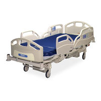
Hill-Rom CareAssist P1170 Service Manual (197 pages)
Bed
Brand:
Hill-Rom
| Category:
Medical Equipment
| Size: 3 MB
Table of Contents
Table of Contents
7
Chapter 1: Introduction
15
Purpose
15
Audience
15
Organization
15
Chapter 2: Troubleshooting Procedures
15
Chapter 3: Theory of Operation
15
Chapter 4: Removal, Replacement, and Adjustment Procedures
16
Chapter 5: Parts List
16
Chapter 6: General Procedures
16
Chapter 7: Accessories
16
Document Symbol Definition
17
Standard Features
18
Emergency CPR Controls
18
Caregiver Siderail Controls
18
Enable Control
18
Lockout Control
19
Bed Up/Down Control
20
Head Up/Down Control
20
Automatic Contour Feature
21
Knee Up/Down Control
21
Trendelenburg and Reverse Trendelenburg Controls
22
Bed Flat Control
23
Dining Chair™ Position
23
Fullchair® Patient Positioning Mechanism
24
Vascular Position
24
Battery Control
25
Standard Casters
25
Brake and Steer Control
26
Head and Foot Siderails
27
Headboard
28
Footboard
28
Patient Position Indicator
28
Equipment Sockets
29
Foot Extension
29
Standard Patient Controls
30
Nurse Call Control (Optional)
30
Bed Exit Control (Optional)
31
Patient Controls (Optional)
32
Nurse Call Control (Optional)
32
Room Light Control (Optional)
32
Reading Light Control (Optional)
32
Volume Control (Optional)
33
Channel Control (Optional)
33
Music Control (Optional)
33
Television Control (Optional)
33
Physical Description
34
Model Identification
39
Safety Tips
40
Warning and Caution Labels
42
Chapter 2: Troubleshooting Procedures
43
Getting Started
43
Initial Actions
44
Problem/Solution Table
44
Function Checks
46
Final Actions
51
No Functions Work
52
Lockout Malfunction
55
Hilow Malfunction
56
Knee Section Malfunction
57
Head Section Malfunction (Excluding Automatic Contour)
58
Battery Backup Malfunction
59
Foot Section Malfunction
60
Trendelenburg/Reverse Trendelenburg Malfunction
62
Bed Connected to AC Power, Brakes Not Applied Detection Malfunction
63
CPR Malfunction
66
Braking Malfunction
67
Steering Malfunction
68
Chapter 3: Theory of Operation
69
Introduction
69
Mechanical System
70
Retractable Head Section
70
Emergency CPR Release
70
Extendable Foot Section
70
Hilow System
70
Casters
71
Braking
71
Steering
71
Head and Footboards
71
Electrical System
72
Power Supply Unit Characteristics
73
Power Stage
73
Function Control
74
Battery Circuit
74
Battery Characteristics
75
Control Logic and Specific Functions
75
Patient Pendant
76
Motor Characteristics
76
Management of the Motors
76
Detection of Bed Not in Low Position
77
Automatic Contour
77
Dining Chair™ Position
77
Detection of Bed Connected to AC Power but Brakes Not Set
77
Trendelenburg/Reverse Trendelenburg
78
Electrical System Wiring Diagram
78
Chapter 4: Removal, Replacement, and Adjustment Procedures
81
Tool and Supply Requirements
81
Sleep Deck
83
Removal
83
Replacement
85
AC Power Cord
86
Removal
86
Replacement
86
Power Supply
89
Removal
89
Replacement
91
Battery
92
Removal
92
Replacement
93
Head Section Motor
95
Removal
95
Replacement
97
CPR Cable
98
Removal
98
Replacement
100
Adjustment
100
Knee Section Motor
101
Removal
101
Replacement
103
Foot Section Motor
104
Removal
104
Replacement
106
Head Hilow Column
107
Removal
107
Replacement
108
4.10 Foot Hilow Column
110
Removal
110
Replacement
112
4.11 Brake Detection Switch
114
Removal
114
Replacement
114
4.12 Brake/Steer Bar
116
Removal
116
Replacement
118
4.13 Caster
120
Removal
120
Replacement
121
4.14 Sidecom® Communication System P.C. Board
123
Removal
123
Replacement
124
4.15 Interface P.C. Board
125
Removal
125
Replacement
126
4.16 Fuses
127
Removal
127
Replacement
127
4.17 Siderail Control P.C. Board
129
Removal
129
Replacement
130
4.18 Patient Pendant
132
Removal
132
Replacement
132
4.19 Patient Pendant Mount
133
Removal
133
Replacement
133
4.20 Bed Exit Switch
134
Removal
134
Replacement
136
Chapter 5: Parts List
137
Service Parts Ordering
137
Exchange Policy
139
In-Warranty Exchanges
139
Out-Of-Warranty Exchanges
139
Warranty
140
Recommended Spare Parts
142
Base Frame
144
Articulating Frame
148
Foot Extension
152
Head Siderail
154
Foot Siderail
158
Footboard and Headboard
160
Plastic Sleep Deck
161
Motor Control Box
162
CPR Cables
164
Control Cables
166
Interface Control Box
168
Chapter 6: General Procedures
171
Cleaning and Care
171
General Cleaning
171
Steam Cleaning
171
Cleaning Hard to Clean Spots
172
Disinfecting
172
Component Handling
172
P.C. Board
172
Lubrication Requirements
173
Preventive Maintenance
174
Preventive Maintenance Schedule
175
Preventive Maintenance Checklist
180
Chapter 7: Accessories
180
Accessories
181
Infusion Support System-P158
182
Installation
182
Oxygen Tank Holder-P27601
183
Installation
183
Removal
183
Standard IV Pole-P2217
184
Installation
184
Removal
184
Mattress Pad Extender-P734EA1
185
Installation
185
Removal
185
Mattress-P731EA3
186
Installation
186
Removal
186
Advertisement
Related Products
Hill-Rom P1190
Hill-Rom Advanta P1600
Hill-Rom P1441A
Hill-Rom P1440B
Hill-Rom P1441B
Hill-Rom P1830
Hill-Rom P1350
Hill-Rom Century+ P1400
Hill-Rom Basic Care P1440
Hill-Rom Basic Care P1441
Hill-Rom Categories
Medical Equipment
Lifting Systems
Sling
Mobility Aid
Indoor Furnishing
More Hill-Rom Manuals
Login
Sign In
OR
Sign in with Facebook
Sign in with Google
Upload manual
Upload from disk
Upload from URL