Advertisement
Quick Links
Estate Swing brand gate openers are a Sequoia Brands, Inc. product.
Please visit www.estateswing.com for manual updates and other product information
This gate opener is low voltage and bolt on specifically designed for homeowner installation.
E-S Allegiant Series
Single Swing and Dual Swing Gate Opener
Do-It-Yourself Installation and Operation Manual
1
Advertisement

Related Manuals for Estate Swing E-S Allegiant Series


Summary of Contents for Estate Swing E-S Allegiant Series
- Page 1 Estate Swing brand gate openers are a Sequoia Brands, Inc. product. Please visit www.estateswing.com for manual updates and other product information This gate opener is low voltage and bolt on specifically designed for homeowner installation. E-S Allegiant Series Single Swing and Dual Swing Gate Opener...
- Page 2 Important: Do not turn the shaft of the operator arm until the post and gate The Estate Swing is only to be used for vehicular swing gates in a Class I setting. brackets are fully installed. Class I: A vehicular gate opener (or system) intended for use in a home of one-to- four single family dwelling, or a garage or parking area associated therewith.
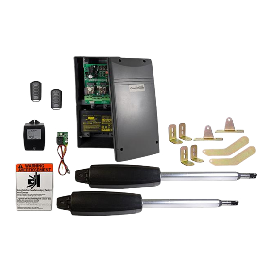
- Page 3 Parts Control box with control board Single Gate Opener Kit with Transformer Charging Setback Templates Warning Sign Remote Gate Bracket transmitter Gate Bracket Hardware 2) 3/8” x 2” Carriage Bolt, Lock washer, Washer, Nut 1) 1/4” x 2” Hex Bolt, Lock Washer, Washer, Nut 1) Clevis pin 1) Cotter Pin] Battery lift for larger...
-
Page 4: Shopping List
Needed Tools and Parts Checklist Shopping List Check off the items as you account for them and if you need to purchase an Group Size 24 Deep Cycle Marine battery and battery terminal wire item add it to the shopping list side on the right connectors (2 sets of connectors). - Page 5 Determine Pull or Push to Open Operation The next steps will be split with pull to open on left and push to open on right PULL TO OPEN: This means the gate oper ator is mount- PUSH TO OPEN: This oper ation is commonly used if your ed on the inside of the property and pulls your gate in towards driveway slopes up after the gate, preventing it from swinging the property.
- Page 6 Determine the setback needed Below are 2 common examples of Pull to Open setback mountings. These Below are 2 common examples of Push to Open setback mountings. These are not the only options for mounting. are not the only options for mounting. Degree Open Degree Open 5.5”...
-
Page 7: Installation
Installation 1. Place one corner of the setback 1. Place one corner of the setback template on the center of the hinge of template on the center of the hinge of the gate. Direct it so it is the gate. Direct it so it is perpendicular from the closed gate. - Page 8 4. Place one of the L shape brackets with 4. Place one of the L shape brackets with the top lined up with the line drawn on the the top lined up with the line drawn on the post in step 3. The side of post the bracket post in step 3.
- Page 9 7. With the gate in the OPEN position, at- 7. With the gate in the CLOSED position, tach the gate opener to the post bracket attach the gate opener to the post bracket assembly and gate bracket. Swing the arm assembly and gate bracket.
- Page 10 Mount the control box and run wires from the gate opener(s) into the box Running wire under the driveway 10. Find a location for the control Needed: box within 5 feet of the operator - Narrow shovel. - ¾’ water pipe no more that 5’ in length (you would need a total number of (or primary operator arm for a dual pipes that would equal your driveway width plus 1’).
- Page 11 Wire the Operator Arm(s) to the Control Board The green terminal strips on the control board are easily removed for wiring. Simply pull straight out on the terminal strip to remove it from the board. It will slide right off. Slide it back on when you are finished with your wiring connections.
-
Page 12: Power Connection
Power Connection 15. Crimp the battery connectors (not included) to the battery wire. The only power connected to the Estate Swing E-S Allegiant control board will be the battery* (not included). Important: Please respect polarity when attaching the battery terminals. Do not cross wires. - Page 13 Programming Piston Extended Position For SINGLE GATE Pull to Open: For SINGLE GATE Push to Open: 17. Remove sticker on end of the arm. 17. Remove sticker on end of the arm. Press/release the SET button. P1 will show Press/release the SET button. P1 will show on the display.
- Page 14 Programming Piston Extended Position For DUAL GATE Push to Open: For DUAL GATE Pull to Open: 17. Remove sticker on end of the arm. 17. Remove sticker on end of the arm. Press/release the SET button. P1 will show Press/release the SET button. P1 will on the display.
- Page 15 22. Set the parameters to match the needed settings. Press/release the SET button to access the parameters. Press/release the ADD or DEC buttons to review or 23. Program remote transmitters to the board. Press/ change the individual parameter settings. Press/release the SET button to move release the learn button.
Need help?
Do you have a question about the E-S Allegiant Series and is the answer not in the manual?
Questions and answers