Table of Contents
Advertisement
Advertisement
Table of Contents

Related Manuals for Estate Swing E-S 1000H Series


Summary of Contents for Estate Swing E-S 1000H Series
- Page 1 EstateSwing.com Plug-in Option E-S 1000H Series INSTRUCTION MANUAL...
- Page 2 Estate Swing Summary of Functions The Estate Swing is only to be used for vehicular swing gates in a Class I setting. Class I: A vehicular gate opener (or system) intended for use in a home of one-to-four single family dwelling, or a garage or parking area associ- ated therewith.
-
Page 3: Table Of Contents
The table of contents are listed to assist you locating a desired section. We do however strongly suggest studying every page of the instruction manual before attempting installation. Section 1: Review of Specifications, Warnings, and Tools Specifications of the Estate Swing and Components Parts List System Overview & Preliminary Checks... -
Page 4: Section 1: Review Of Specifications, Warnings, And Tools
Section 1: Review of Specifications, Warnings, and Tools E-S 1000H Series Instruction Manual... -
Page 6: Specifications
The above chart represents the maximum weight and length combinations that this gate opener can handle. The lengths and weights are either for a single gate or for a single leaf of a dual gate. E-S 1000H Series Instruction Manual... -
Page 7: Parts List
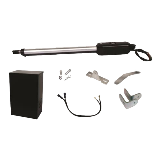
1 - 5/16”x 1 3/8” Hex bolt, washer, nut 2 - 3/8”x 2” Carriage bolt, washers, nut 2 - 3/8”x 2” Carriage bolt, washers, nut 1 - 1/4” x 2” Hex bolt, washers, nut 1 - 1/4” x 2” Hex bolt, washers, nut E-S 1000H Series Instruction Manual... - Page 8 Photo sensors and a flashing light indicating gate movement is recommend- ed for safety purposes. 1,2 Estate Swing Operator • 3 Photocells (not included) • 4 Control board • 5 N/A • 6 Push but- ton opening device (not included) • 7 Receiver extension (not included)• 8 12Vdc flashing lamp (not included) •...
-
Page 9: Tools Needed For Installation
12V, 35Ah or higher deep cycle marine battery Positive post, bracket or door stop. Although the Estate Swing 1000 features built in limit switches it is highly recommended to have positive stops. • 16 gauge, 2 conductor stranded direct burial low voltage wire will be required to run power to your battery. -
Page 10: Section 2: Installation Of Mounting Brackets
Section 2: Installation of Mounting Brackets E-S 1000H Series Instruction Manual... -
Page 12: Manual Operation
To Manually Change Position of Piston: 1) Remove pin as seen below. 2) The shaft can now be turned to open and close manually. 3) Replace pin to exit manual operation. E-S 1000H Series Instruction Manual... - Page 13 This means the gate operator is mounted on the inside of the property and pulls your gate in towards the property. If you are going to use push to open operation “X” out the next 3 pages and use the push to open section instructions. E-S 1000H Series Instruction Manual...
- Page 14 To determine the position of the gate mounting bracket the right: (above is for the post mounting bracket) refer to step 13 in 6” 8½” 110° the section “Installation of operator” 7 ½” 9” 16 ½ 100° 9 ½” 9 ½” 90° E-S 1000H Series Instruction Manual...
-
Page 15: Installation Of Operator-Pull To Open
Using the template, mark the boomerang bracket for cutting. [See Fig. 2] 4) Cut off the excess length (if any) of the boomerang bracket using a sawzall or hack- saw. Alternate Mounting Option E-S 1000H Series Instruction Manual... - Page 16 Mark then drill and attach the bracket using 3/8” carriage bolts. [See Fig. 4] Check “L” shaped bracket for levelness before putting in the second bolt. Fig 4 Continue on next page. E-S 1000H Series Instruction Manual...
- Page 17 Fig 6 using a 5/16” drill bit in an area behind the first hole. Secure the hole with a 5/16” bolt and the provided nuts and lock washers. [See Fig. 6] Continue on next page. E-S 1000H Series Instruction Manual...
- Page 18 [See Fig. 8] Note: Secure the center hole of the gate Fig 8 bracket with a bolt. E-S 1000H Series Instruction Manual...
- Page 19 This operation is commonly used if your driveway slopes up after the gate, prevent- ing it from swinging in. This means the gate operator is mounted on the inside of the property and pushes your gate out away from the property. E-S 1000H Series Instruction Manual...
- Page 20 2 inches away from the 7 ½” 9” 16 ½ 100° gate in both the open and closed position. (variations significantly reduces the length and 9 ½” 9 ½” 90° weight capacity of the operator) E-S 1000H Series Instruction Manual...
-
Page 21: Installation Of Operator-Push To Open
Using the template, mark the boomerang bracket for cutting. [See Fig. 2] 4) Cut off the excess length (if any) of the boomerang bracket using a sawzall or hack- saw. Alternate Mounting Option 2.10 E-S 1000H Series Instruction Manual... - Page 22 Mark then drill and at- tach the bracket using 3/8” carriage bolts. [See Fig. 4] Check “L” shaped bracket for levelness before putting in the second bolt. Fig 4 Continue on next page. 2.11 E-S 1000H Series Instruction Manual...
- Page 23 5/16” drill bit in an area behind the first hole. Secure the hole with a 5/16” bolt Fig 6 and the provided nuts and lock washers. [See Fig. 6] Continue on next page. 2.12 E-S 1000H Series Instruction Manual...
- Page 24 [See Fig. 8] Fig 8 Note: Secure the center hole of the gate bracket with a bolt. 2.13 E-S 1000H Series Instruction Manual...
- Page 25 Section 3: Gate Operator Mounting, Wiring Motors & Power E-S 1000H Series Instruction Manual...
-
Page 27: Mounting Gate Operator(S) & Finding Limits
4) Temporarily secure the front of the arm with a clevis pin. You will be locating and setting the limits in the next page. E-S 1000H Series Instruction Manual... - Page 28 7) Move the other limit switch on the bot- tom to line up with the washer. Once you set the limits, secure the front side of the gate operator with the clevis pin and the cotter pin. E-S 1000H Series Instruction Manual...
-
Page 29: Control Box & Running Wires
TIP: If junction box is located in a high mois- 8) Install and secure cover. ture area, apply petroleum jelly on to the See next page for instructions on running wire under terminal block to protect from moisture. the driveway. E-S 1000H Series Instruction Manual... -
Page 30: Easy Wiring Under Driveway
6 inches of pipe is sticking out from under the driveway. On the opposite side of the drive- way look for a wet spot or water bubbling up, dig to find the end of the pipe. E-S 1000H Series Instruction Manual... - Page 31 The terminals come closed. Be sure not to mis- take this for open and insert the wires below the terminal clamp. This will lack the conductivity to complete the circuit. E-S 1000H Series Instruction Manual...
- Page 32 Wiring the Operator Arm(s) For a dual gate use the provided wire to connect the secondary motor to the control board. Pull to Open (Opening out towards property) It is important to choose the correct type operation type E-S 1000H Series Instruction Manual...
- Page 33 For a dual gate use the provided wire to connect the secondary motor to the control board. Push to Open (Opening out towards the street) It is important to choose the correct type operation type E-S 1000H Series Instruction Manual...
-
Page 34: Temporary Safety Jumpers & Dip Switch Settings
1 OFF. If the dip switch is set to on, the gate will au- to-reclose after turning it on without any intentional activation on your part. E-S 1000H Series Instruction Manual... -
Page 35: Power
Power The only power connected to the Estate Swing E-S1000H control board will be the battery. Important: Please respect polarity when attaching the battery terminals. Do not cross wires. Allow a minimum of 4’ of wire between the charge board and the transformer for this option. -
Page 36: Section 4: Start Up And Operation
Section 4: Start Up and Operation E-S 1000H Series Instruction Manual... -
Page 38: First Run
Re-attach gate opener to the gate bracket. Activate using Push 1 button (as shown above) The gate should run open. Press Push 1 again and it should run closed. The gate is now set up for regular use. E-S 1000H Series Instruction Manual... -
Page 39: Determine Run Time
Record your run time below. Actual Run Time: _____________________________ Note: The above example is for Pull-To-Open operation. If you are installing your gate opener as Push-To-Open then the open limit will be reverse of the above. E-S 1000H Series Instruction Manual... -
Page 40: Operating Parameters Customization
6. LED shows P6: P6 is the delay for automatic re-close from the open position – this option needs to be turned on using the dip switch on the board. The options are 0-99 seconds. E-S 1000H Series Instruction Manual... -
Page 41: 433 Plug-In Receiver
Please note that you will find a factory in- stalled jumper wire connected on the receiver. Leave this jumper wire in place. One of the terminals that has the jumper wire will have the White wire add- ed to the terminal. E-S 1000H Series Instruction Manual... - Page 42 DO NOT mount the receiver anyplace that water may access it from another angle. For ex- ample: Do not mount near sprinklers. Do not mount the receiver horizontally. Do not mount the receiver near a flat surface where water could splash upwards. E-S 1000H Series Instruction Manual...
- Page 43 Section 5: Maintenance, Troubleshooting & Accessories E-S 1000H Series Instruction Manual...
-
Page 45: Maintenance
Maintenance 1) Lubricate the rear pivot and front pivot of the bracket. 2) Lubricate the gate hinges about every 3 months and also check for levelness of gate. E-S 1000H Series Instruction Manual... -
Page 46: Troubleshooting
While the motor is running look at the multi-meter reading again. The voltage should not drop more than 0.2 volts g. If all the above are true then we can rule out battery and wire from battery to board and determine the chip needs to be replaced. E-S 1000H Series Instruction Manual... - Page 47 The motor will not move and the display reads PH PH stands for Photo Cell. On an Estate Swing gate opener the safety terminal (Photo) is a Nor- mally Closed connection. What this means is the gate opener needs the Photo terminal to be connected to the ground terminal in order to operate.
- Page 48 If one arm is moving and the other is not, you can swap the center and right hand fuse to see if the issue swaps motor and ensure the fuse is the issue if you do not have a multi-meter to test the fuse. Continue on next page. E-S 1000H Series Instruction Manual...
- Page 49 A device that is wired into accessory terminal PUSH2 is making a connection to the COM terminal. The gate opener is a single gate and the number 2 dip switch is in the up position. Continue on next page. E-S 1000H Series Instruction Manual...
- Page 50 (push to open) the limit switch for the closed position is in by the motor and the limit switch for the open position is at the end of the arm. Gate or post bracket has shifted. Continue on next page. E-S 1000H Series Instruction Manual...
- Page 51 This will ensure the slave will close first. (keep in mind this will affect overall run time and they may need to be increased as well) Continue on next page. E-S 1000H Series Instruction Manual...
- Page 52 3 seconds without something in the gate’s path. This is because obstructions are detected through amperage usage by the motor and the reaction of the systems power supply to that resistance. Continue on next page. E-S 1000H Series Instruction Manual...
- Page 53 (P3, leverage, lubrica- tion, etc.) are not investigated and corrected they could be a contributing factor. And if eliminated the wind issue could lessen or go away. Continue on next page. E-S 1000H Series Instruction Manual...
- Page 54 Swap the first and third limit switch wire in the limit1 block for the master operator or single gate. Swap the first and third wire in the limit2 block if the issue is on the secondary operator. 5.10 E-S 1000H Series Instruction Manual...
- Page 55 You can now repeat this procedure for other buttons of the same remote or buttons on oth- er remotes. Continue on next page. 5.11 E-S 1000H Series Instruction Manual...
- Page 56 Learn1 button. Learn2 is pair to Channel2, which this channel is not utilized in the instruction manual. Please consult estate swing if you wish to utilize Channel2 to activate a different device. To fix this error if you have programmed to Learn2 instead of Learn1, first clear Learn2: Press and hold the Learn2 button, the learn light will illuminate, continue to hold the Learn2 button until the learn light turns off.
- Page 57 The battery continually reaches LU and is a solar installation It is either not enough incoming power to charge the battery, the positioning of the panel or the size of the battery. Continue on next page. 5.13 E-S 1000H Series Instruction Manual...
- Page 58 The display does not show AU in the open position with dip switch 1 on (up) The dip switch only take effect after power down and back up 5.14 E-S 1000H Series Instruction Manual...
- Page 59 If the display is showing OP but the gate is beginning to close the motor wires are backward. Swap the position of the motor leads L1 and L2 for the appropriate motor that is having the issue. 5.15 E-S 1000H Series Instruction Manual...
- Page 60 Repeat this procedure with the piston retracting and the gate in the closed position. 5.16 E-S 1000H Series Instruction Manual...
- Page 61 Many times we can come up with solutions to issues by seeing pictures that relay information that is impossible to relay through a phone conversation. Below are examples of control board pictures and motor pictures that we will be looking for: Pictures shown are actual customer photos 5.17 E-S 1000H Series Instruction Manual...
-
Page 62: Control Board Overview
6. When stopped mid cycle - momentary contact will open the gate. 7. When open with auto-reclose off - momentary contact will have no effect. 8. When closing - momentary contact will re-open the gate. E-S 1000H Series Instruction Manual... - Page 63 6. When stopped mid cycle - momentary contact will open the gate. 7. When open with auto-reclose off - momentary contact will have no effect. 8. When closing - momentary contact will re-open the gate. E-S 1000H Series Instruction Manual...
- Page 64 5. When closing - momentary contact will re-open the gate. PUSH 1 and PUSH 2 – these terminals can hold as many normally open connections as needed, they will be wired in parallel. They are used for keypads, push buttons, universal receivers, etc. E-S 1000H Series Instruction Manual...
- Page 65 Solenoid lock output - 12VDC (4 Amp max) A = Positive B = Negative Fuses: (2) F1 = 8A 250V, protects power to motors, fused individually F2 = 2A 250V, protects power to accessory 12V terminals E-S 1000H Series Instruction Manual...
- Page 66 At this point no accessories or remotes will be able to activate the gate opener until the gate opener is reset by disconnecting pri- mary power battery. E-S 1000H Series Instruction Manual...
- Page 67 12V Power positive (+) or (12V) or (PWR) of exit device = +12V terminal of PHOTO block on gate opener control board. 12V Power Negative (-) or (GND) or (PWR) or Shield wire of exit device = GND terminal of PHOTO block on gate opener control board. E-S 1000H Series Instruction Manual...
- Page 68 Connect positive lead of the power supply directly to the positive lead of the mag lock. Connect negative lead of the power supply to the N/C terminal of the relay. Connect the COM terminal of the relay to the negative lead of the mag lock. E-S 1000H Series Instruction Manual...
Need help?
Do you have a question about the E-S 1000H Series and is the answer not in the manual?
Questions and answers