Table of Contents
Advertisement
Advertisement
Table of Contents

Subscribe to Our Youtube Channel
Related Manuals for BMR SFU-0302-SSE


Summary of Contents for BMR SFU-0302-SSE
- Page 1 Frequency Converter SFU-0302-SSE...
-
Page 2: Table Of Contents
RPM configuration Starting and Stopping the Frequency Converter Remote Controlled Configuration of Direction of Rotation Safety Stop Functions Connection to Profibus Calibration and Configuration using Windows Software Connection Examples Faults, Trouble-Shooting EMC (Electro-Magnetic Compatibility) Mechanics, Views + Dimensions BMR GmbH 2014-03-17... -
Page 3: Introduction
In addition, both a.c. and d.c. motors can be operated by this high frequency converter. BMR GmbH 2014-03-17... -
Page 4: Description And Features
Galvanic separation of all interfaces from each other and from the network / motor potential • Short-circuit-protected • User-friendly configuration and control using optional Windows Software for the PC • Automatic spindle detection, if supported by the spindle BMR GmbH 2014-03-17... -
Page 5: Block Diagram
SFU-0302 SSE M a n u a l – 5– 3. Block Diagram BMR GmbH 2014-03-17... - Page 6 SFU-0302 SSE M a n u a l – 6– BMR GmbH 2014-03-17...
-
Page 7: Technical Data
130mm, height: 320mm (with mounting straps: 380mm), depth: 262mm Weight 7 kg Protection IP20 Operating conditions max. ambient temperature 40°C, no humidity CAUTION: To avoid severe motor / spindle damage, select correct motor / spindle characteristic ! BMR GmbH 2014-03-17... -
Page 8: Safety Precautions And Warnings
The EMC of a machine or device is affected by all connected components (cables, wiring, etc..) and for this reason, installation and connection of the device should only be carried out by qualified personnel. BMR GmbH 2014-03-17... -
Page 9: Connections, Interfaces And Pinout
The same assignment is also possible for the analogue measured data and control data at the analogue I/O pin. The standard allocations of operational parameters, their outputs, control signals and inputs, are listed in the following table. BMR GmbH 2014-03-17... - Page 10 The digital inputs require a high level of 24 V for correct function (PLC standard level). • Hall sensor output level: 0-24V (24V level.) • Analogue input voltage range: 0...10V • The +24V output can be used as a power supply for this type of electronic spindle interface. BMR GmbH 2014-03-17...
- Page 11 Ohms causes the switching of digital output overtemp spindle and safety cut-out following the programmed delay . • The Hall sensor input operates from input signal levels of +/- 1V within the common mode range of 0..10V. • The 5V output can be used as a power suppl. BMR GmbH 2014-03-17...
-
Page 12: Spindle Connection At Screw Terminals
Control cables, supply cables and motor cables must be isolated from each other. Shielded cables are to be preferred ! 6.3 RS232 (D-Sub 9pin male) Description Function receive-data (data to converter) send-data (data from converter) Ground use a standard zero-modem-cable for connection to PC BMR GmbH 2014-03-17... - Page 13 SFU-0302 SSE M a n u a l – 13– 6.5 Screw Terminals Mains Spindle screw terminals figure 1 BMR GmbH 2014-03-17...
-
Page 14: Functions, Commissioning, Operation
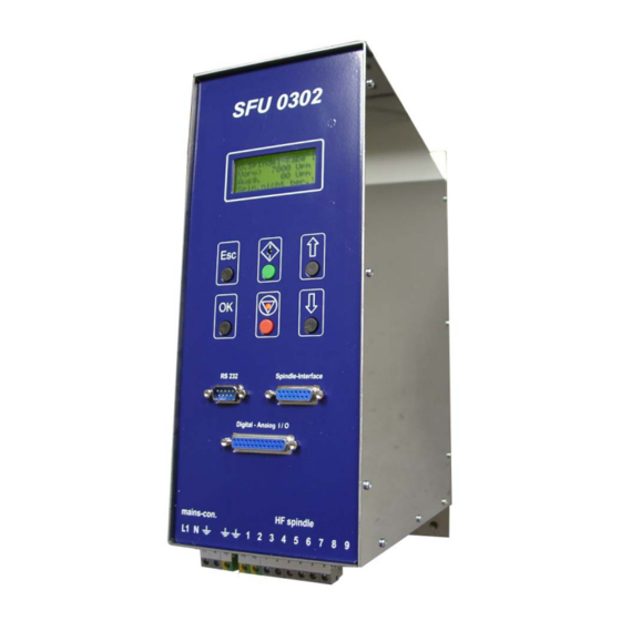
7.1 Front Panel LCD 4-rows Button START Button UP Button STOP Button DOWN figure 2 The front keys allow access to following functions: • Start / Stop manually • RPM-control via UP / DOWN keys • Spindle characteristic selection BMR GmbH 2014-03-17... -
Page 15: Lcd Display
R S 2 3 2 E r r o r • Error spindle characteristic not valid D a t a E r r o r : • Error encoder/hall sensor E n c o d e r e r r o r : BMR GmbH 2014-03-17... -
Page 16: Configuration Via The Front Keys
A voltage of 0V leads to a standstill and a voltage higher than 0V leads to a startup upto the desired revolution. An input voltage of 4V and a scaling as above mentioned lead to a revolution of 40.000RPM. The settings must be downloaded into the converter with the button write data. BMR GmbH 2014-03-17... -
Page 17: Starting And Stopping The Frequency Converter
Windows platform. The level of control this provides is almost at machine-level, so that this option is more appropriate for error evaluation and special control features via PC. If you need to control the SFU-0302 remotely, please contact BMR or your local distributor for assistance and the RS232 command-set. -
Page 18: Safety Stop Functions
After an error flag has occurred, it must be cleared by a Start/Stop sequence or a digital error reset with a digital input (in form ‘digital inputs’ Error reset). 4 seconds after error reset, the device is ready for operation again. BMR GmbH 2014-03-17... -
Page 19: Connection To Profibus
Analogue input and output can be done via Profibus. With the help of a pointer any value can be addressed. Please see the documentation of command interpreter Profibus in folder BMR-GSD. BMR GmbH... - Page 20 1. Start-up frequency converter and connect via RS232 interface. 2. Start-up program SFUTerminal.exe The interface is then configured automatically. A connected frequency converter is detected and all data transfer parameters are synchronised. The description can be found in the help menu and manual of "SFU-Terminal". BMR GmbH 2014-03-17...
-
Page 21: Connection Examples
(given in the field „min rpm“ in the according spindle diagram). It will stop, when either the dig. start pin wents low or the voltage at the analogue pin is lower than the given BMR GmbH 2014-03-17... - Page 22 M a n u a l – 22– min. rpm. Eg. When 10V are applied at the analogue input 1 and the dig. start is high, the motor will start and accelerate up to ist max rpm. BMR GmbH 2014-03-17...
- Page 23 SFU-Terminal the Temperature Sensor button the evaluation of the temperature sensor is activated in the spindle Temperature sensor of the spindle > Change spindle characteristic defective > Disable in spindle characteristic menu in SFU-Terminal the Temperature Sensor button BMR GmbH 2014-03-17...
- Page 24 > Verify at USB cables that it's length is not SFU-Terminal the longer than 2m Converter is not detected and not > Try to use original BMR cables, only. recognized In case of using RS232 > Use the USB-Interface at the PC together with a USB-RS232 converter.
- Page 25 > In the spindle characteristic the value of > Spindle cable is too long the start voltage has to be increased. -> contact BMR With activated spindle test, a test current is send via spindle cable to the spindle by applying a voltage at output lines.
- Page 26 > Increase value for start voltage in the spindle by applying a voltage at output spindle characteristic lines. In case that this current is too -> contact BMR low, or a wrong spindle characteristic selected, it does not match to the > Deactivate function "Spindle test"...
-
Page 27: Emc (Electro-Magnetic Compatibility)
Supply cables, motor cables and control cables must be completely isolated from each other. Where crossing cannot be avoided, cables should be laid at 90° to each other. • The control cable should be laid as far away as possible from the load cable. BMR GmbH 2014-03-17... -
Page 28: Mechanics, Views + Dimensions
SFU-0302 SSE M a n u a l – 28– 13. Mechanics, Views + Dimensions BMR GmbH 2014-03-17... - Page 29 SFU-0302 SSE M a n u a l – 29– this page is left intentionally left blank BMR GmbH 2014-03-17...
- Page 30 SFU-0302 SSE M a n u a l – 30– Walpersdorfer Straße 38 D 91126 Schwabach Germany Tel.: +49 (0)9122 63148-0 Fax.: +49 (0)9122 63148-29 e-mail: Info@bmr-gmbh.de Internet: www.bmr-gmbh.de Subject to technical alterations. 2014-03-24 BMR GmbH 2014-03-17...
Need help?
Do you have a question about the SFU-0302-SSE and is the answer not in the manual?
Questions and answers