Advertisement
Quick Links
Advertisement

Subscribe to Our Youtube Channel
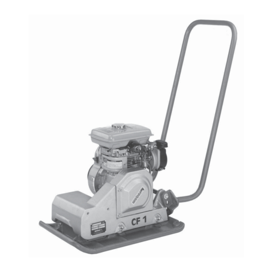
Summary of Contents for Weber mt CF 1
- Page 1 SERVICE INFORMATION Repair Instructions CF 1 Service Information 2006 Section 3*** Page 1...
- Page 2 SERVICE INFORMATION Repair Instructions CF 1 Table of Contents Illustration ....................3 Preface ....................... 4 Disassembly ..................5 Reassembly ..................11 Section 3*** Page 2 Service Information 2006...
- Page 3 SERVICE INFORMATION Repair Instructions CF 1 Preface Before starting your repair work, carefully read these repair instructions. Carefully follow all instructions and always carry out the described operations in the indicated order. The safety precautions prescribed for repair work must be followed in order to avert injury to persons and/or damage to material property.
- Page 4 SERVICE INFORMATION Repair Instructions CF 1 Illustration shaft tapered roller bearing shim shaft seal eccentric O-ring seal cover plug washer O-ring seal guard bearing cover V-belt pulley Section 3*** Page 4 Service Information 2006...
- Page 5 SERVICE INFORMATION Repair Instructions CF 1 1. Disassembly Undo the fastening screws (2) to remove the V-belt guard (1). Figure 1 Undo the fastening screws (1) of the engine (2) and push the engine to the front. Figure 2 Remove the V-belt (1).
- Page 6 SERVICE INFORMATION Repair Instructions CF 1 Put the base plate (1) with integrated vibrator (2) at an appropriate place. Figure 4 a Slightly tilt the base plate (1) with integrated vibrator (2) and remove the oil drain screw (3). Danger to the Environment! Choose a drain pan having a sufficient capacity to catch all the used oil.
- Page 7 SERVICE INFORMATION Repair Instructions CF 1 Remove the fastening screw (1) of the V-belt pulley (2). Figure 7 Screw a hexagon socket screw (1) in the eccentric shaft to protect the thread. Figure 8 Put the extractor (1) between the two flanks of the V-belt pulley (2) and remove the V-belt pulley from the eccentric shaft by means of the extractor.
- Page 8 SERVICE INFORMATION Repair Instructions CF 1 Remove the 4 fastening screws (1) of the housing cover (2). Figure 10 Use appropriate screw drivers or fitting levers and press the housing cover (1) from the vibrator housing. Be careful not to damage the sealing surface.
- Page 9 SERVICE INFORMATION Repair Instructions CF 1 Use appropriate screw drivers or fitting levers to remove the housing cover (1) from the vibrator housing (2). Figure 13 Take the eccentric (1) out of the vibrator housing. Figure 14 Clamp the eccentric (3) in a vise.
- Page 10 SERVICE INFORMATION Repair Instructions CF 1 Clamp the eccentric in a vise (3). Put the extractor (1) against the bearing (2) and remove the bearing. Take care that the extractor cannot slip - risk of injury! Figure 16 Section 3*** Page 10...
- Page 11 SERVICE INFORMATION Repair Instructions CF 1 2. Reassembly Clamp the eccentric shaft in a vise. Use an appropriate tool and carefully knock the bearing (1) onto the shaft. Figure 17 Use an appropriate tool (2) to drive the outer ring (1) of the bearing into the housing cover (3).
- Page 12 SERVICE INFORMATION Repair Instructions CF 1 Apply grease onto the O-ring seal (1) of the housing cover (2). Figure 20 Use an appropriate tool (2) to drive the outer ring (1) of the bearing into the vibrator housing (3). Figure 21 Fit the housing cover (1).
- Page 13 SERVICE INFORMATION Repair Instructions CF 1 Put the eccentric (1) into the vibrator housing (2). Figure 23 Put the housing cover (1) with the shaft seal (2) onto the vibrator housing. The cast characters (3) must face upwards. Figure 24 Use an appropriate tool to fit the housing cover (1) onto the vibrator housing (2).
- Page 14 SERVICE INFORMATION Repair Instructions CF 1 Fasten the housing (1) with 2 screws (2) at the top. Figure 26 Fit the V-belt pulley (1) together with the retaining ring (2) and the fastening screw (3) onto the eccentric shaft. The fastening screw (3) must feature a vent hole in order to ensure the pressure compensation in the vibrator housing.
- Page 15 SERVICE INFORMATION Repair Instructions CF 1 Use an appropriate tool (2) to fit the eccentric shaft (1) without play. Figure 29 Use an appropriate tool to fit the bearing's outer ring (1) without play. Figure 30 Fit the O-ring seal (1) onto the housing cover (2).
- Page 16 SERVICE INFORMATION Repair Instructions CF 1 Spread the O-ring seal (1) with grease. Figure 32 Use a depth slide gauge (1) to determine the distance between the cover's collar (2) and its upper surface (3). Figure 33 Measure the depth between the housing (1) and the bearing outer ring (2).
- Page 17 SERVICE INFORMATION Repair Instructions CF 1 Adjust the axial play by means of the shim ring (1) . Axial play 0.45 mm. Figure 35 Fit the housing cover (1) . Characters faced upwards. Figure 36 Top the system up with oil according to the operating instructions manual.
- Page 18 SERVICE INFORMATION Repair Instructions CF 1 Slightly knock on the V-belt pulley (1) to drive in the eccentric shaft again. Figure 38 Check the axial play as shown. Figure 39 Section 3*** Page 18 Service Information 2006...


Need help?
Do you have a question about the CF 1 and is the answer not in the manual?
Questions and answers