Table of Contents
Advertisement
Quick Links
Advertisement
Table of Contents

Related Manuals for Weber mt MC 85


Summary of Contents for Weber mt MC 85
- Page 1 Operating and Maintenance Manual MC 85 0142410 - 0142411...
- Page 2 Before starting There is a rating plate identifying the machine including designation, type, serial numbers, year of construction, mass, and rated power. Note down this information so that you can recreate the rating plate should the plate be lost 1 Designation 2 Type ............
-
Page 3: Table Of Contents
Contents 1. Introduction ........................4 2. Description ........................5 3. Technical data ......................... 6 4. Safety ..........................8 4.1. Information and safety stickers ................14 5. Operation........................17 5.1. Prior to initial use ....................17 5.2. Operating positions on the machine ..............18 5.3. -
Page 4: Introduction
Store these documents carefully. Turn to your Weber MT dealer if you require any additional information. Found on the last page of this manual is a QR code. Scan it to acquire the current contact addresses of all Weber MT branches. -
Page 5: Description
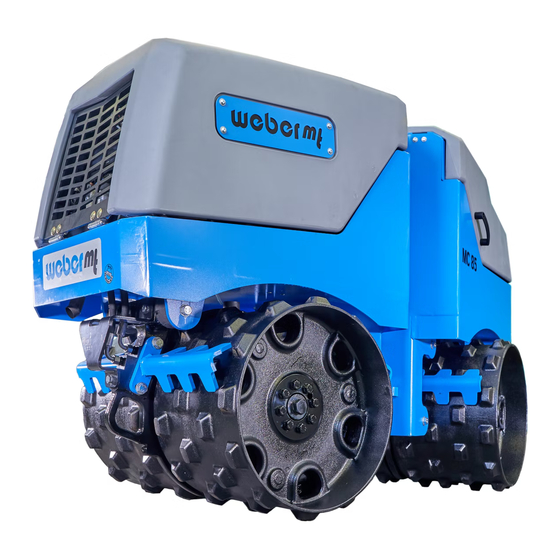
2. Description The machine The machine is a radio-controlled, type MC 85 trench roller with articulated steering. The machine is composed of two separate halves which are interlinked by a so-called articulated joint. The front section houses two drums, an exciter, the diesel engine and the hydraulic pumps. -
Page 6: Technical Data
3. Technical data MC 85 Weight 1618 Dead weight [kg] Operating weight CECE [kg] 1628 Dimensions Overall length [mm] 2018 Height [mm] 1300 Drum width [cm] Drum diameter [cm] Axle base [cm] Drive Engine manufacturer Kubota Type D 1005 Performance at operating speed in accordance with ISO 3046-1 [kW] 14.3... - Page 7 3. Technical data MC 85 Vibration Front + Rear Vibrating drum Drive concept Hydr. Frequency [Hz] Compaction force, high amplitude [kN] Compaction force, low amplitude [kN] Operation Remotely operated Noise emissions in accordance with 2000/14/EC Sound pressure level LPA [dB(A)]...
-
Page 8: Safety
Malfunctions that impair safety must be eliminated without delay. The MC 85 roller is designed exclusively for the following operations: – Compacting work during the construction of channels and pipes – Structure backfilling... - Page 9 Requirements on This soil compactor may only be driven by suitable operators the operator who are of legal age. They must be instructed on how to operate the machine by the owner or by the owner’s assigned personnel. The operator must comply with traffic regulations. If instructions that affect safety are given by the owner or third parties, then the operator must be authorized to reject these instructions.
- Page 10 Changes and conversions are prohibited unless made with original and conversions Weber MT spare parts. If the machine is modified with other acces- sories without the approval of Weber MT, the manufacturer will not assume liability for any resulting personal injury or property damage. All maintenance and repairs must be carried out with original Weber MT spare parts. Untested spare parts may affect the...
- Page 11 During operation To avoid personal injury and property damage, the operator must monitor the entire surroundings at all times. It will not suffice to only monitor the immediate danger area as the machine may tip suddenly and unexpectedly on account of potential landslides or other types of unforeseen changes in the ground. The occurrence of unusual noises may point to a defect.
- Page 12 Maintenance The roller must be inspected in accordance with the corresponding implementation conditions and operating conditions to ensure its operationally safe status. This inspection should be performed as needed by an expert – however, no less than once a year or every 150 operating hours. The findings of the inspection must be stored in writing until the time of the next inspection.
- Page 13 Safe handling of Combustion engines pose a particular risk during operation. combustion engines Their exhaust emissions contain carbon monoxide, a colorless and odorless gas that is extremely hazardous, which, if inhaled even briefly, can cause unconsciousness and death. Therefore, never inhale the exhaust gas. When operating the machine in trenches or poorly ventilated locations, the operator must not be in the immediate vicinity of the machine.
-
Page 14: Information And Safety Stickers
4.1. Information and safety stickers Sticker Meaning All threaded unions must be checked for firm seat on a regular basis and, particularly, after initial use. The fuel tank may only be fueled with diesel. Wear ear protection. Lashing eyelet for securing during transport. To lash the machine down, place the strap across the drums as shown. - Page 15 4.1. Information and safety stickers Sticker Meaning Lifting ring for lifting the machine. – Near-field shutdown in a perimeter of 2 m around the machine. – Sound power level 105 dB (A). – Read the operating manual. – Danger of suffocation when exhaust gas is inhaled or during operation in closed rooms.
- Page 16 4.1. Information and safety stickers Sticker Meaning Danger of crushing injuries to the hands while closing the hoods. Crushing hazard in the area of the articulated joint. Risk of burns at the hot exhaust. This tank may only be filled with hydraulic oil. Rating plate identifying the machine including designation, Description type, serial numbers, year of...
-
Page 17: Operation
5. Operation 5.1. Prior to initial use Preparing the machine Remove all packaging material. for initial use Check all components for visible damage. Do not start the machine if detecting visible damage. Contact the responsible dealer. Check if the shipment of the machine and its components is complete. -
Page 18: Operating Positions On The Machine
5.2. Operating positions on the machine B 1001-0120 1 The radio remote control The radio remote control is used to control the machine. It is explained in more retail in the section “The radio remote control”. 2 The key switch The key switch is used to switch the power supply to the machine on or off. -
Page 19: The Radio Remote Control
5.3. The radio remote control B 1002-0120 1 The steering lever The steering lever steers the machine in the desired direction. Deflect to the left The machine steers to the left. Deflect to the right The machine steers to the right. 2 The drive lever The drive lever controls the forward and backward movement of the machine. - Page 20 4 The vibration selector The vibration selector switch switches the vibration system on or off. switch It has three positions. Deflect to the front The vibration is turned on permanently. Set to middle position Automatic vibration has been selected. The vibration is activated by driving and steering commands and stops shortly after the last driving and steering command. Deflect to the back The vibration is switched off.
-
Page 21: Before Starting Work
5.4. Before starting work Perform the following tasks before starting to work in order to prevent failures or excessive wear. Visual inspections Engine and cooling system for leaks Hydraulic tank and lines for leaks Fuel system for leaks Rubber buffers for crack formation Plug connections of the power grid for firm seat Other damage Function tests Emergency stop system of the radio remote control... -
Page 22: Testing The Safety Devices
Unlock the emergency stop switch on the remote control by turning it in arrow direction. The machine can be started again. If the safety devices are not operational, stop working with the machine immediately and promptly rectify the cause. For this purpose, contact Weber MT’s service organization. -
Page 23: Operation
5.6. Operation WARNING Risk of injury for unauthorized persons in the danger area! The near-field shutdown system provides protection only to the operator, not to third parties! Always ensure that everyone keeps at a safety distance of at least 2 meters around the machine. Sound the horn if necessary. Do not resume operation until everyone has left the danger area. -
Page 24: The Vibration System
5.7. The vibration system Selecting the The “Vibration force” selector switch makes it possible to choose vibration force between a strong and a weak vibration force. If the vibration force is changed with the vibration system running, Weak the change will take affect after a safety period of 4 seconds vibration in order to prevent damage to the machine. Strong vibration Automatic vibration The machine is equipped with an automatic vibration system. -
Page 25: Notices On Operation
6. Notices on operation 6.1. Position of The switches on the radio remote control are arranged in such the operator a way that they map the movements of the machine when the operator is positioned behind the machine. This means, for instance, that the machine will move away from the operator when the drive lever is deflected to the front. When the steering lever is deflected to the right, the machine will move to the right. -
Page 26: Shut-Off Devices
6.2. Shut-off devices The near-field The radio system is equipped with a near-field shutdown system. shutdown system If the operator holding the radio remote control moves up to the machine closer than 2 meters, the machine will stop all driving and steering commands and the vibration. The display of the remote control indicates in which area the minimum distance was not observed. -
Page 27: The Battery Of The Radio Remote Control
6.3. The battery of the radio remote control The battery of the radio remote control is composed of three nickel- metal hydride cells (NiMH) with a total capacity of 2.2 Ah. It can be charged any time without any memory effect even if not drained completely. If fully drained, the battery will take approx. 9 hours to recharge. -
Page 28: Safe Driving
6.4. Safe driving ATTENTION Different environmental conditions and driving styles may affect driving stability. Observe the following information to prevent the machine from tipping over. Surface conditions Always pay attention to the operating surface during operation. If in doubt, check the bearing capacity of the ground first. To ensure safe operation, always adjust the speed, vibration and direction of travel to the environmental conditions. - Page 29 Steering on inclines Avoid steering when operating on inclines. The machine may tip over if the operator steers while driving up an incline. If it is necessary to steer during operation on an incline, the operator must make sure to move the straight part of the machine towards the edge or the slope.
-
Page 30: Messages On The Radio Remote Control
6.5. Messages on the radio remote control Message Cause Response of the machine Remedy Remove the machine Near-field from the safety area Driving and steering shutdown system commands are stopped was tripped drive in the opposite direction The remote Driving and steering shutdown system Step closer to the machine commands are stopped... - Page 31 Message Cause Response of the machine Remedy The engine is shut down Clean the air filter, see Air filter is fouled 10 minutes after the error section “Maintenance” is reported. Engine start is The engine starts following Engine preheats delayed slightly the preheating process. Error in Find the fault. For this Engine switches off, the electronic purpose, contact Weber...
-
Page 32: Transport
7. Transport B 1004_2-0120 7.1. Lifting the machine The machine can be lifted for loading onto a vehicle. Before lifting the machine, make sure the articulated joint has been locked with the locking lever (4) (see section “Maintenance”). Lift the machine using the lifting ring (1). Use only slings that possess the appropriate carrying capacity. -
Page 33: Cleaning
Center of gravity When lifting and securing the machine on a transport vehicle, observe position number 3 as it indicates the position of the center of gravity. Slow maneuvering The machine offers an option for driving at a speed slower than operating speed for the purpose of loading the machine with a ramp and for maneuvering it precisely. -
Page 34: Storage
9. Storage Storage at the The machine is weather-protected and can be stored at the construction site construction site over night. To store it at the construction site, the machine must be parked on a level surface outside of trenches or depressions. If parking on a slight slope cannot be avoided, the machine must be secured against rolling by placing wedges in front of the drums. -
Page 35: Maintenance
10. Maintenance General information The section below contains instructions that need to be observed for regular maintenance. Read these instructions carefully and follow them in order to prevent downtimes of the machine caused by excessive wear or damage to the machine. Also read the safety instructions relevant to machine maintenance before you begin with the maintenance work. -
Page 36: Maintenance Overview
10.1. Maintenance overview Activity Interval Initial maintenance / 25 operating hrs Daily maintenance Every 50 operating Every 150 operating Every 300 operating Every 600 operating 10.2.4 See section 10.2.3 10.2.3 10.2.3 10.2.6 10.2.7 10.2.12 10.2.5... - Page 37 10.2.9 10.2.14 10.2.14 10.2.14 10.2.6 10.2.8 10.2.13 Kubota Kubota 10.2.10...
-
Page 38: Description Of The Maintenance Operations
10.2. Description of the maintenance operations 10.2.1. Opening / closing the hood CAUTION Danger of burn injuries at hot engine and its attachments. Especially the exhaust is very hot after operation. Allow the combustion engine to cool down sufficiently before starting work. Do not reach into the area of the hot engine. Shut off the machine as described in section 5.8. -
Page 39: Checking Fluid Levels
10.2.3. Checking fluid levels ATTENTION Danger of material damage from improper checking of the fluid levels. Only check the fluid levels when at operating temperature and with the machine parked horizontally. Shut off the machine as described in section 5.8. Open the hoods as described in section 10.2.1. To check the engine oil level, wait for approx. 2 minutes after switching off the combustion engine. - Page 40 Check the hydraulic oil level using the view glass (4). The fill level must be at ¾ of the view glass. If this is not the case, proceed as described in section 10.2.10. The coolant level can be checked through the slightly transparent expansion reservoir (5). The coolant level must range between the two markings (6).
-
Page 41: Changing The Engine Oil
10.2.4. Changing the engine oil Only drain the engine oil when at operating temperature. Shut off the machine as described in section 5.8. Open the hoods as described in section 10.2.1. Place a suitable collection vessel (1) under the oil drain (2). Open the oil drain (2) and allow the oil to drain into the collection vessel (1). -
Page 42: Changing The Engine Oil Filter
10.2.5. Changing the engine oil filter Shut off the machine as described in section 5.8. Open the hoods as described in section 10.2.1. Drain engine oil as described in section 10.2.4. Unscrew the engine oil filter (1). ATTENTION Risk of environmental damage. Catch the residual oil and the used engine oil filter using a suitable collection vessel and properly dispose of waste oil in accordance with environmental protection regulations. -
Page 43: Cleaning / Changing The Air Filter
10.2.6. Cleaning / changing the air filter Shut off the machine as described in section 5.8. Open the hoods as described in section 10.2.1. WARNING Risk of breathing difficulties, including suffocation, from the dust produced while blowing out the air filter. Only blow out the air filter in well-ventilated locations. Wear a dust mask. Open the brackets (1) to remove the cap (2). Remove the air filter (3) and clean / replace it. Clean the air filter with compressed air – max. 5 bar. Blow the dirt out of the air filter from the inside out. Should complete cleaning with compressed air no longer be possible on account of damp or oily dirt, the air filter must be replaced. -
Page 44: Draining The Fuel Filter
10.2.7. Draining the fuel filter Shut off the machine as described in section 5.8. Open the hoods as described in section 10.2.1. Place a suitable collection vessel under the fuel filter. Open the drain valve (2) and allow the water to drain into the collection vessel. Close the drain valve (2). ATTENTION Risk of environmental damage. -
Page 45: Changing The Fuel Filter
10.2.8. Changing the fuel filter Shut off the machine as described in section 5.8. Open the hoods as described in section 10.2.1. Place a suitable collection vessel under the fuel filter (1). Open the drain valve (2) and allow the fuel to drain into the collection vessel. Unscrew the fuel filter (1). ATTENTION Risk of environmental damage. Properly dispose of the used fuel filter in accor- dance with environmental protection regulations. -
Page 46: Changing The Hydraulic Oil Filter
10.2.9. Changing the hydraulic oil filter Shut off the machine as described in section 5.8. Open the hoods as described in section 10.2.1. Open the cap (1). Slowly pull the hydraulic oil filter (2) with the protective cage (3) out of the enclosure (4). Pull the hydraulic oil filter (2) out of the protective cage (3). Slide the protective cage (3) back into the enclosure (4). ATTENTION Risk of environmental damage. -
Page 47: Changing The Hydraulic Oil
10.2.10. Changing the hydraulic oil Shut off the machine as described in section 5.8. Secure the articulated joint as described in section 10.2.2. Open the hoods as described in section 10.2.1. Place a suitable collection vessel under the hydraulic oil drain (1). Open the hydraulic oil drain (1) and allow the hydraulic oil to drain into the collection vessel. -
Page 48: Changing The Exciter / Drive Oil
10.2.11. Changing the exciter / drive oil Only drain oil from the exciter / drive when at operating temperature. Shut off the machine as described in section 5.8. Secure the articulated joint as described in section 10.2.2. Secure the machine to keep it from overturning. Loosen the dirt scrapers (1) on either side of the drum (2). - Page 49 WARNING Risk of severe injury if the machine rolls away or tips over. Secure the machine with suitable means to keep it from rolling and overturning. Use suitable lifting gear to lift the machine as shown on one side by approx. 50 cm. Open the oil filler plug (5).
-
Page 50: Checking / Adjusting The Fan V-Belt
10.2.12. Checking / adjusting the fan V-belt CAUTION Danger of burn injuries at hot engine and its attachments. Allow the combustion engine to cool down sufficiently before starting work. Shut off the machine as described in section 5.8. Open the hoods as described in section 10.2.1. Check the tension of the fan V-belt (1). The tension is correct if the belt can be depressed by approx. -
Page 51: Changing The Fan V-Belt
10.2.13. Changing the fan V-belt CAUTION Danger of burn injuries at hot engine and its attachments. Allow the combustion engine to cool down sufficiently before starting work. Shut off the machine as described in section 5.8. Open the hoods as described in section 10.2.1. Loosen the set screw (1) and the fastening screw (2) of the alternator (3) and relieve the fan V-belt (4). -
Page 52: Lubrication Chart
10.2.14. Lubrication chart Shut off the machine as described in section 5.8. Lubricate the individual positions of the machine as specified in the table below. Use grease that complies with the specification “KP2K-20” according to DIN 51502. Lubricating point Quantity 1 Articulated joint (top + bottom) 2 strokes 2 Cylinder on the left 2 strokes 3 Cylinder on the right 2 strokes 4 Drum bearings 3 strokes... -
Page 53: Operating Fluids And Fill Levels
10.3. Operating fluids and fill levels Operating material Assembly Quantity Summer Winter SAE 10W-30 SAE 15W-40 (–10 °C to 25 °C) On request for other Engine oil 3.5 l temperature ranges Quality: API – CF MIL-L-2104C Water-coolant Concentration 50 % Cooling system Coolant concentration 3.1 l... -
Page 54: Final Shutdown And Disposal
10.4. Final shutdown and disposal ATTENTION Risk of environmental damage from the operating fluids of the machine. Carry out the work steps below carefully and dispose of all oper- ating fluids in accordance with statutory regulations. Take up any spilled operating fluids immediately and dispose of them properly. Drain fuel tank. Drain coolant. Drain hydraulic oil completely. Drain engine oil. Drain oil from exciter / drive. Remove the battery and properly dispose of it in accordance with statutory regulations. -
Page 56: Hydraulic Circuit Diagram
10.5 Hydraulic circuit diagram... - Page 57 Part Units Designation Diesel engine Tandem gear pump Control block driving / steering Pressure relief valve 2/2-way valve 4/3-way valve 4/3-way valve Lowering brake valve Check valve Check valve Throttle Ø 1.8 3.10 Pressure relief valve 3.11 Deadweight tester 10 bar Control block vibration system Pressure relief valve 3/2-way valve...
- Page 58 Notiz / note:...
- Page 59 Notiz / note:...
- Page 60 facebook.com/WeberMT youtube.com/MyWeberMT Weber Maschinentechnik GmbH Im Boden 5 – 8, 10 · 57334 Bad Laasphe · Germany Phone +49 2754 398 0 · Fax +49 2754 398 101 info@webermt.de · www.webermt.de 085103151-104 / MC 85_2020-05 Original instructions...
Need help?
Do you have a question about the MC 85 and is the answer not in the manual?
Questions and answers