Salda RIS EKO 3.0 1200 PE 3.0 Mounting And Installation Instruction
Source: salda.lt/en, vetter-lufttechnik.de
Table of Contents
Advertisement
Advertisement
Table of Contents

Related Manuals for Salda RIS EKO 3.0 1200 PE 3.0


Summary of Contents for Salda RIS EKO 3.0 1200 PE 3.0
- Page 1 RIS 12002500 P EKO 3.0 MOUNTING AND INSTALLATION INSTRUCTION...
-
Page 2: Table Of Contents
1. CONTENT 2. SYMBOLS AND MARKING 3. SAFETY INSTRUCTIONS AND PRECAUTIONS 4. INFORMATION ABOUT THE PRODUCT 4.1. DESCRIPTION 4.2. DIMENSIONS AND WEIGHT 4.3. TECHNICAL DATA 4.4. OPERATING CONDITIONS 4.5. STANDARD PACKAGE OF COMPONENTS 4.6. DESCRIPTION OF COMPONENTS 5. INSTALLATION 5.1. RECEPTION OF GOODS 5.2. -
Page 3: Symbols And Marking
2. SYMBOLS AND MARKING Warning – pay attention Additional information Apply the auxiliary label on the unit (on an easily accessible location) or on the dashed location of the technical manual in order to keep the important information about the unit. Figure. -
Page 4: Safety Instructions And Precautions
3. SAFETY INSTRUCTIONS AND PRECAUTIONS Read these instructions very carefully before installing and using this equipment. Installation, connection and maintenance should be carried out Main safety rules Danger • of the device have stopped. • Make sure that the fans are not accessible through air ducts or branch openings. •... -
Page 5: Information About The Product
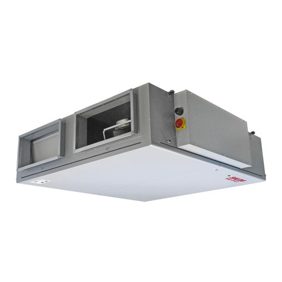
4. INFORMATION ABOUT THE PRODUCT 4.1. DESCRIPTION Not suitable for operation in pools, saunas and other similar premises. 4.2. DIMENSIONS AND WEIGHT Figure 4.2.1. RIS 1200 P EKO 3.0 dimension Figure 4.2.2. RIS 1900-2500 P EKO 3.0 dimension RIS 1200-2500 P EKO 3.0 v2020.1 EN |... - Page 6 1200 PE 1200 PE 1200 PE 1200 1900 PE 1900 PE 1900 PE 1900 2500 PE 2500 PE 2500 PE 2500 RIS EKO 3.0 12.0 18.0 [mm] 1550 1550 1550 1550 1750 1750 1750 1750 1850 1850 1850 1850 [mm] 1397 1397 1397...
-
Page 7: Technical Data
4.3. TECHNICAL DATA RIS EKO 3.0 1200 PE 3.0 1200 PE 6.0 1200 PE 9.0 1200 PW Exhaust air fan phase/voltage [50 Hz/VAC] ~1, 230 ~1, 230 ~1, 230 ~1, 230 [kW/A] 0,38/2,5 0,38/2,5 0,38/2,5 0,38/2,5 speed [min 3370 3370 3370 3370 control input... -
Page 8: Operating Conditions
RIS EKO 3.0 2500 PE 4.5 2500 PE 9.0 2500 PE 18.0 2500 PW Exhaust air fan phase/voltage [50 Hz/VAC] ~1, 230 ~1, 230 ~1, 230 ~1, 230 [kW/A] 0,72/3,1 0,72/3,1 0,72/3,1 0,72/3,1 speed [min 2800 2800 2800 2800 control input [VDC] 0-10 0-10... -
Page 9: Description Of Components
4.6. DESCRIPTION OF COMPONENTS Figure. 4.1. RIS 1200 P EKO 3.0 Figure. 4.2. RIS 1900-2500 P EKO 3.0 1 - Plate heat exchanger; 2 - Supply fan; 3 - Exhaust fan; 4 - By-pass damper RIS 1200-2500 P EKO 3.0 v2020.1 EN |... -
Page 10: Installation
5. INSTALLATION 5.1. RECEPTION OF GOODS Each device is carefully checked before transportation. When receiving the goods, checking the devices for any damage made during transporta- tion is recommended. If any damage to the unit is observed, immediately contact the representatives of a transport company. Please inform the representative of the manufacturer, if any deviation of the device is noticed. -
Page 11: Unpacking
L1>L2 Figure 5.2.2. Lifting by forklift RIS 1900-2500 P EKO 3.0 In order to prevent damage to the casing, only a product placed on a pallet should be lifted. Figure 5.2.3. Lifting RIS 1200 P EKO 3.0 Figure 5.2.4. Lifting RIS 1900-2500 P EKO 3.0 5.3. -
Page 12: Piping And Instrumentation Diagram
Figure 5.3.1. Unpacking RIS 1200 P EKO 3.0 Figure 5.3.2. Unpacking RIS 1900-2500 P EKO 3.0 5.4. PIPING AND INSTRUMENTATION DIAGRAM * KE1 - only in electrical version; * KV1 - used in water version; ** Possible to control. | EN RIS 1200-2500 P EKO 3.0 v2020.1... -
Page 13: Mounting
THE LIST OF COMPONENTS Plate heat exchanger Supply air fan Exhaust fan Exhaust air temperature sensor Supply air temperature sensor Extract air temperature and humidity sensor sensor Computer Electric heater* By-pass damper Outdoor air damper actuator Exhaust air damper actuator Outdoor air temperature sensor Ventilated premises MB-Gateway... -
Page 14: Unit Placing And Mounting Positioning Requirements
5.5.1. UNIT PLACING AND MOUNTING POSITIONING REQUIREMENTS 1,5xL 5.6. CEILING-MOUNTING OF THE UNIT Figure 5.6.1. Ceiling-mounting of the unit ⌀ Figure 5.6.2. Drainage system installation (øD=150 mm) thermal isolation. 5.7. CONNECTION OF THE AIR DUCT • • • and noise level, you can increase the diameter. •... -
Page 15: Connection Of The Unit To Electric Network
5.8. CONNECTION OF THE UNIT TO ELECTRIC NETWORK • • • • The unit must be earthed according to electrical equipment installation regulation. • • • • made during transportation. • The manufacturer does not assume any liability for personal injuries and property damage due to nonconformance with the provided instructions. -
Page 16: Maintenance
6. MAINTENANCE 6.1. SAFETY INSTRUCTION Unplug the unit from the mains before opening the door (disconnect the power plug from the outlet or in case a automatic 6.2. GENERAL RECOMMENDATIONS FOR VENTILATION SYSTEM MAINTENANCE COMPONENT DURING START-UP AT LEAST EVERY 6 MONTHS Filters device indications. -
Page 17: Filters Maintenance
6.4. FILTERS MAINTENANCE direction. tion manual or on our website www.salda.lt 6.5. FAN MAINTENANCE • • The fan should be inspected and cleaned at least once per year. • • Proceed to maintenance and repair after any fan rotation is stopped. -
Page 18: Heater Maintenance
6.7. HEATER MAINTENANCE • • • • • If necessary, electric heater can be removed. Disconnect the electrical connector from the heater and remove the heater. 6.8. CONTROL BOARD MAINTENANCE • • • • Remove control board. • and connector to corresponding connection terminal and connector. | EN RIS 1200-2500 P EKO 3.0 v2020.1... -
Page 19: Control
BMS over Modbus TCP/IP FLEX BMS over BACnet TCP/IP 7.2. DEVICE FUNCTIONS cation and SALDA AIR mobile application. For unit control instructions, refer to the operation manual of the existing control device. RIS 1200-2500 P EKO 3.0 v2020.1 EN |... -
Page 20: Accessories
8. ACCESSORIES RIS EKO 3.0 1200 PE 1200 PW 1900 PE 1900 PW 2500 PE 2500 PW OCR 500x250 ACC000059 ACC000059 OCR 700x300 ACC000061 ACC000061 OCR 700x400 ACC000062 ACC000062 LJ-E 50-25 FIT000423 FIT000423 LJ/E 70x30 FIT000959 FIT000959 LJ-E 70-40 FIT000761 FIT000761 LJ-PG 50-25 FIT000313... - Page 21 ACC000269 ACC000269 ACC000269 ACC000269 ACC000269 ACC000269 Remote control panel ACC000270 ACC000270 ACC000270 ACC000270 ACC000270 ACC000270 FLEX Remote control panel ACC000271 ACC000271 ACC000271 ACC000271 ACC000271 ACC000271 ST-SA-Control Control Remote control panel ACC000272 ACC000272 ACC000272 ACC000272 ACC000272 ACC000272 Stouch ACC004460 ACC004460 ACC004460 ACC004460 ACC004460 ACC004460...
-
Page 22: Connection Of Accessories
AKS 355-10 FIT000421 FIT000421 FIT000421 FIT000421 AKS 355-6 FIT000276 FIT000276 FIT000276 FIT000276 AKS 355-9 FIT000277 FIT000277 FIT000277 FIT000277 AKS 500-12 FIT000447 FIT000447 AKS 500-9 FIT000281 FIT000281 SKS 50-25 FIT000299 FIT000299 Silenc- SKS 70-40 FIT000302 FIT000302 FIT000302 FIT000302 500x250x1000- ACC000126 ACC000126 2x100 500x250x900- ACC000121... -
Page 23: Room Co Transmitter Installation Recommendation
8.1.3. ROOM CO TRANSMITTER INSTALLATION RECOMMENDATION 5 0 c m i n . min. 60 cm max. 400m If the duct CO2 transmitter is used, it must be installed in the extract air duct. To install duct transmitters, hole drilling tools are required . -
Page 24: Connection Of Remote Control Panel Or Modbus
Wiring diagram for RIS PW EKO 3.0 M2 – Spring-return damper actuator. M3 – Open/Close damper actuator. Upon activation of outputs X16:17, X16:20, the dampers open, Upon is deactivated, the supply air damper closes. 8.1.6. CONNECTION OF REMOTE CONTROL PANEL OR MODBUS 8.1.7. - Page 25 M5 – Water cooler valve actuator. M6 – Water heater calve actuator. FA – Fire alarm. TL – Outdoor air temperature sensor (TJK-10K). AT1 – Electric heater automatic protection. TJ – Supply air temperature sensor (TJK-10K). RT1 – Electric heater manual protection. TE –...
- Page 26 Figure 8.1.8.2. RIS 1200 PE 6.0-9.0 EKO 3.0 | EN RIS 1200-2500 P EKO 3.0 v2020.1...
- Page 27 Figure 8.1.8.3. RIS 1200PW EKO 3.0 RIS 1200-2500 P EKO 3.0 v2020.1 EN |...
- Page 28 Figure 8.1.8.4. RIS 1900PE 3.0 EKO 3.0 | EN RIS 1200-2500 P EKO 3.0 v2020.1...
- Page 29 Figure 8.1.8.5. RIS 1900 PE 6.0-12.0 EKO 3.0, RIS 2500 PE 4.5-9.0-18.0 EKO 3.0 RIS 1200-2500 P EKO 3.0 v2020.1 EN |...
- Page 30 Figure 8.1.8.6. RIS 1900-2500 PW EKO 3.0 | EN RIS 1200-2500 P EKO 3.0 v2020.1...
-
Page 31: Possible Faults And Troubleshooting
9. POSSIBLE FAULTS AND TROUBLESHOOTING FAILURE CAUSE EXPLANATION / CORRECTIVE ACTIONS No supply voltage Unit is not operating leakage relay is active (if installed by the installer) matic protection Check if fans are rotating Air supply heater or pre-heater is not operat- ing or malfunctioning (if installed) Manual safety device is activated MUST be contacted to identify and eliminate... -
Page 32: Ecodesign Data Table
10. ECODESIGN DATA TABLE RIS EKO 3.0 1200 PE 3.0 1200 PE 6.0 1200 PE 9.0 1200 PW Declared typology bidirectional bidirectional bidirectional bidirectional Type of drive Variable Variable Variable Variable Type of HRS recuperative recuperative recuperative recuperative 80,2 80,2 80,2 80,2 /s ]... - Page 33 RIS EKO 3.0 2500 PE 4.5 2500 PE 9.0 2500 PE 18.0 2500 PW Declared typology bidirectional bidirectional bidirectional bidirectional Type of drive Variable Variable Variable Variable Type of HRS recuperative recuperative recuperative recuperative 80,4 80,4 80,4 80,4 /s ] 0,64 0,64 0,64...
-
Page 34: Declaration Of Confimity
11. DECLARATION OF CONFIMITY Manufacturer SALDA, UAB LT-78109 Šiauliai, Lithuania Tel.: +370 41 540415 www.salda.lt RIS * EKO 3.0 Machinery Directive 2006/42/EC EMC Directive 2014/30/EU Low Voltage Directive 2014/35/EU Ecodesign Directive 2009/125/EC RoHS 2 Directive 2011/65/EU Ecodesign requirements for ventilation units Nr. 1253/2014 Energy labeling of residential units Nr. -
Page 35: Warranty
12. WARRANTY date. such damage. damaged by installing the control system. 4.1. mechanical damage; 4.2. damage caused by entering outside objects, materials, liquids; lation and mounting regulations, deliberate or careless users or third-party behavior. days and deliver the equipment to manufacturer. Delivery costs should be covered by customer. Manufacturer reserves the right to change this technical passport any time without prior notice, if some typographic errors or inaccurate information is found, as well as after improving the apps and/or the devices. - Page 36 Once per year** Every 3-4 Filter replacement months** Look at the product label. ** - At least. NOTE. The customer shall be required to complete the Product Maintenance Table. MANUALS IN OTHER LANGUAGES https://select.salda.lt/file/ https://select.salda.lt/file/ https://select.salda.lt/file/ https://select.salda.lt/file/ https://select.salda.lt/file/ ris1200-2500pekode ris1200-2500pekodk ris1200-2500pekofr ris1200-2500pekolt ris1200-2500pekopl https://select.salda.lt/file/...
Need help?
Do you have a question about the RIS EKO 3.0 1200 PE 3.0 and is the answer not in the manual?
Questions and answers