Advertisement
Quick Links
Advertisement

Related Manuals for Vaisala RI41


Summary of Contents for Vaisala RI41
- Page 1 M212988EN-A User Guide Vaisala Ground Check Device RI41...
- Page 2 All legally binding obligations are change without prior notice. set forth exclusively in the applicable contract or in the relevant set of General Conditions of Vaisala Local rules and regulations applicable to the (www.vaisala.com/policies). products and services may vary and they shall...
- Page 3 Preparing a sounding..................9 Preparing radiosonde with ground check device..........9 4.1.1 Connecting radiosonde with RI41............... 9 4.1.2 Displaying ground check status for RS41-SGP(E) using RI41....11 4.1.3 Displaying ground check status for RS41-SG(E) with RI41.....12 4.1.4 Tuning radiosonde frequency..............13 4.1.5 Configuring radiosonde frequencies............14...
- Page 4 Document versions (English)................5 Table 2 Related manuals.......................5 Table 3 RI41 spare parts......................22 Table 4 RI41 operating environment................23 Table 5 RI41 inputs and outputs..................23 Table 6 RI41 mechanical specifications................23 Table 7 RI41 reference sensors..................23 Table 8 RI41 compliance..................... 24...
- Page 5 Chapter 1 – About this document 1. About this document 1.1 Version information This document provides instructions for Vaisala Ground Check Device RI41. Table 1 Document versions (English) Document code Date Description M212988EN-A October 2023 First version. 1.2 Related manuals Table 2 Related manuals Document code...
- Page 6 Indicates that you need to take some notes during the task. 1.4 Trademarks Vaisalaâ and DigiCORAâ are registered trademarks of Vaisala Oyj. All other product or company names that may be mentioned in this publication are trade names, trademarks, or registered trademarks of their respective owners.
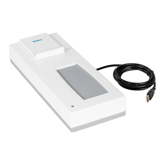
- Page 7 2. Product overview 2.1 Vaisala Ground Check Device RI41 Vaisala Ground Check Device RI41 is available in 2 models: RI41, and the similar RI41‑B, which is equipped with a barometer module. The RI41‑B is used together with RS41 radiosondes with in-built pressure sensors, such as the RS41‑SGP. During the ground preparation procedure, the reference barometer in the RI41‑B is used to adjust the measurement of the...
- Page 8 The ground check device is powered on when it is connected to the computer. For more information on how to configure RI41 as the ground check device to be used as the connection between the radiosonde and the sounding workstation, see MW51...
- Page 9 4.1 Preparing radiosonde with ground check device 4.1.1 Connecting radiosonde with RI41 Before you connect the radiosonde to the ground check device, connect the ground check device to the sounding workstation by using a USB cable and turn on the computer and log in to DigiCORA.
- Page 10 RI41 User Guide M212988EN-A 1. Place the radiosonde on the ground check device carefully. Make sure that you place the radiosonde on so that you place the back end (antenna end) of the radiosonde on the device first. CAUTION! Make sure that the radiosonde sensor boom does not hit the support plate on the ground check device, as this may damage the sensor boom.
- Page 11 When you are ready to release the balloon, switch the radiosonde back on. 4.1.2 Displaying ground check status for RS41-SGP(E) using RI41 The ground check phases are slightly different depending on the radiosonde model and the ground check device.
- Page 12 • Temperature: In-built functional temperature check • Humidity: Preparation of humidity sensor, cooling, and physical zero humidity check • Pressure: Manual entry of the pressure reference value, or with RI41-B, retrieve pressure reference value automatically from barometer module in the ground check device •...
- Page 13 Chapter 4 – Preparing a sounding The preparation status changes to Preparation completed when all the preparation steps are successful and it is then safe to remove the radiosonde from the ground check device. The Radiosonde status shows if any error occurs and causes the preparation to fail. 4.1.4 Tuning radiosonde frequency If needed, you can manually tune the radiosonde frequency while DigiCORA is preparing the radiosonde.
- Page 14 RI41 User Guide M212988EN-A If you want to set pre-selected frequencies, see Configuring radiosonde frequencies (page 14). 4.1.5 Configuring radiosonde frequencies You can configure pre-selected (default) frequencies for the radiosonde. During ground check, DigiCORA automatically sets the frequency to the radiosonde. You can configure more than one frequency as backup.
- Page 15 Chapter 4 – Preparing a sounding 2. To add frequencies, type a value in the input field and select Add. The values must be within 400.16–405.99 range, (maximum of 2 decimal places). You can remove frequencies by selecting the remove button X. If you want to reorder the list, use the arrow up and arrow down buttons.
- Page 16 RI41 software update again. 1. In the GC41/RI41 Updater window, select Update. 2. The update command has now been sent to RI41 and you must wait for 10 seconds. 3. The update begins. A progress bar is displayed in the Updater window.
- Page 17 Chapter 5 – Maintaining hardware 5.2 Calibrating RI41-B barometer module To calibrate RI41-B barometer module you need to have a reliable reference barometer. 1. Log in to DigiCORA as DigiCORA Administrator. 2. Go to Administration > System overview > Ground check device and select Calibration.
- Page 18 5.3.1 Removing old barometer module CAUTION! Disconnect RI41-B from the workstation before replacing the barometer module. 1. Remove screws (6 pcs) on the bottom of RI41-B with the Torx screwdriver and remove the bottom cover. Barometer module inside RI41-B Barometer module pressure tube...
- Page 19 Chapter 5 – Maintaining hardware 2. Remove the barometer module. 3. Use the flathead screwdriver to loosen the pressure tube. 4. Pull the pressure tube out of the tube fitting piece...
- Page 20 5.3.2 Attaching new barometer module 1. Attach the new barometer module’s pressure tube by pushing it to the tube fitting piece. 2. Check the connector positions on the barometer module and place the barometer module in the correct position in RI41-B.
- Page 21 Chapter 5 – Maintaining hardware 3. Push the barometer module in place. 4. Attach the RI41-B bottom cover using the Torx T20 screwdriver and reconnect RI41-B to the workstation.
- Page 22 RI41 User Guide M212988EN-A 6. Spare parts 6.1 RI41 spare parts RI41 is replaced as a whole device. In RI41-B, the barometer module is available as a spare part. Table 3 RI41 spare parts Code Description RI41 Ground check device RI41-B Ground check device with barometer module...
- Page 23 13.56 MHz Short range wireless communication RF technique Communication link range 0.04 m (1.57 in) Electrical interface USB 1.1/2.0 Cable with connector Table 5 RI41 inputs and outputs Property Description/Value Power supply Input Through USB interface Voltage 5 V DC Typical current 300 mA Table 6 RI41 mechanical specifications...
- Page 24 RI41 User Guide M212988EN-A Property Description/Value Long term stability 0.1 hPa/year The recommended in-field calibration interval for barometer module is one year Table 8 RI41 compliance Property Description/Value EU directives and regulations Radio Equipment Directive, RED (2014/53/EU) RoHS Directive (2011/65/EU) amended by 2015/863...
- Page 25 Chapter 8 – RI41 regulatory statements 8. RI41 regulatory statements 8.1 FCC compliance statement This equipment has been tested and found to comply with the limits for a Class B digital device, pursuant to Part 15 of the FCC rules. These limits are designed to provide reasonable protection against harmful interference in a residential installation.
- Page 26 RI41 User Guide M212988EN-A 2. This device must accept any interference, including interference that may cause undesired operation of the device. L’émetteur/récepteur exempt de licence contenu dans le présent appareil est conforme aux CNR d’Innovation, Sciences et Développement économique Canada applicables aux appareils radio exempts de licence.
- Page 27 Conditions of Sale for details of the warranty for each product. Technical support Contact Vaisala technical support at helpdesk@vaisala.com. Provide at least the following supporting information as applicable: • Product name, model, and serial number •...
- Page 30 www.vaisala.com...
Need help?
Do you have a question about the RI41 and is the answer not in the manual?
Questions and answers