Table of Contents
Advertisement
Quick Links
Features
l
Receives and transmits AES/EBU, S/PDIF
and EIAJ-340 compatible digital audio
l
Convenient access to the Serial Audio Input
Port and Serial Audio Output Port through
headers.
l
Runs from a single 5 Volt supply.
l
Crystal supplied to allow operation at 48 kHz,
sample rate.
l
Digital patch area.
I
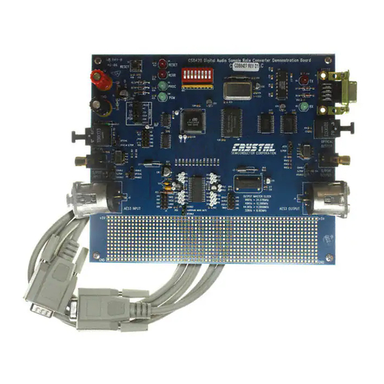
Optical In
S/PDIF In
AES 3 In
Preliminary Product Information
P.O. Box 17847, Austin, Texas 78760
(512) 445 7222 FAX: (512) 445 7581
http://www.cirrus.com
Evaluation Board for CS8427
Amtel
µC
CS8427
This document contains information for a new product.
Cirrus Logic reserves the right to modify this product without notice.
Description
The CDB8427 is designed to allow rapid evaluation of
the CS8427. The board is set up for easy connection to
an Audio Precision or a Rohde and Schwarz test system.
Input and output data formats may independently be set
to either AES/EBU, or S/PDIF with either optical or coax-
ial physical format.
Separate headers are provided so the Serial Audio Input
Port and Serial Audio Output Port may be interfaced to
off board circuits.
Windows 98 PC software provides a GUI interface to
make configuration easy. The software communicates
through the PC's RS232 port to a micro-controller on the
evaluation board that controls the CS8427. All the possi-
ble software modes of the CS8427 may be tested.
ORDERING INFORMATION
CDB8427
Copyright Cirrus Logic, Inc. 2000
(All Rights Reserved)
CDB8427
Evaluation Board
RS232 port to PC
Optical Out
S/PDIF Out
AES 3 Out
JAN '00
DS477DB1
1
Advertisement
Table of Contents

Related Manuals for Cirrus Logic Crystal CDB8427


Summary of Contents for Cirrus Logic Crystal CDB8427
- Page 1 AES 3 In AES 3 Out This document contains information for a new product. Preliminary Product Information Cirrus Logic reserves the right to modify this product without notice. Copyright Cirrus Logic, Inc. 2000 JAN ‘00 P.O. Box 17847, Austin, Texas 78760...
-
Page 2: Table Of Contents
(electronic, mechanical, photographic, or otherwise) without the prior written consent of Cirrus Logic, Inc. Items from any Cirrus Logic website or disk may be printed for use by the user. However, no part of the printout or electronic files may be copied, reproduced, stored in a retrieval system, or transmitted, in any form or by any means (electronic, mechanical, photographic, or otherwise) without the prior written consent of Cirrus Logic, Inc.Furthermore, no part of this publication may be used as a basis for manufacture... -
Page 3: Overview
CDB8427 1. OVERVIEW applications information for the Atmel micro-con- troller are available at http://www.atmel.com. The CDB8427 evaluation board contains a CS8427 and the supporting circuitry necessary for it to op- Crystal Oscillators erate. The input and output options include AES3 There are positions for two crystal oscillators on and S/PDIF in optical and coaxial formats. -
Page 4: Table 1. System Connections
CDB8427 CONNECTOR INPUT/OUTPUT SIGNAL PRESENT Input +5 Volt power Input Ground connection from power supply OPTICAL INPUT Input Digital Audio Interface optical input S/PDIF INPUT Input Digital Audio Interface coaxial input AES3 INPUT Input Digital Audio Interface XLR input RS232 Input/Output Parallel RS232 port for connection to serial port of PC OPTICAL OUTPUT... -
Page 5: Cdb8427.Exe Quick Start Guide
CDB8427 2. CDB8427.EXE QUICK START GUIDE Starting up the software: 1) Double-click on CDB8427.exe or its shortcut. Setting up the hardware: 2) If you get errors right away, the COM port 1) Connect the CDB8427 to a 5V DC power sup- needs to be set properly. -
Page 6: Cdb8427.Exe User's Guide
CDB8427 3. CDB8427.EXE USER’S GUIDE To access additional details about each block, click the left mouse button on the desired block. This Main Window will display a control panel for the selected block. The CDB8427 Control Panel allows you to view If you click outside the boxes, you will bring up the and access the data flow configuration of the Board Setup control panel, as shown on the next... -
Page 7: Board Setup
CDB8427 Board Setup NOTE: Most commands accept either hexadecimal (indicated by either a "0x" prefix or "h" suffix) or The Board Setup panel has some very useful func- decimal parameters. tions, including setting the COM Port used by the used for single line comments application, resetting the CS8427 from software, as script scriptfile call an external script file named... -
Page 8: Figure 3. Cs8427 Digital Audio Transceiver
/RST SFMT1 SUP2 SFMT0 APMS S/AES SUP3 SUP1 TCBLD CDIN SUP4 .01uF MUTE SUP0 SUP5 R14 6.2K 47UH OPT1 OPT2 .1uF .1uF C D O U T CCLK PHONO-JACK TRANSFORMER HDR3X1 CS8427_SPI TP28 TRANSFORMER TP27 .1uF PHONO-JACK C D O U T CCLK TP26 R16 110... -
Page 9: Figure 4. Atmel Avr Risc Micro-Controller
.1uF .1uF .1uF .1uF .1uF .1uF .1uF 74HC574 HM628512 1uF 50V 1uF 50V 74HC573 74VHC125 LED_G D[0-7] A[8-14] 8x 47K PA2(AD2) S/AES PA1(AD1) PA0(AD0) MUTE T1 IN T 1 O U T R1 IN R1 OUT SFMT1 PF7(ADC7) SFMT0 PF6(ADC6) T2 IN T 2 O U T CONNECTOR DB9... -
Page 10: Figure 5. Power Supplies And Reset Circuit
2 Ohms /RESET 100uF 6.3V .1uF BAT85 FERRITE BEAD 74VHC125 /RST BAT85 /PGM P6KE6.8A 100uF 6.3V .1uF LED_R BLACK 74VHC125 BAT85 MRST SW_MOM .01uF Figure 5. Power Supplies and Reset Circuit... -
Page 11: Figure 6. Silkscreen
Figure 6. Silkscreen... -
Page 12: Figure 7. Top Pcb
Figure 7. Top PCB... -
Page 13: Figure 8. Bottom Pcb
Figure 8. Bottom PCB...
Need help?
Do you have a question about the Crystal CDB8427 and is the answer not in the manual?
Questions and answers