Table of Contents
Advertisement
Quick Links
Smart encoders & actuators
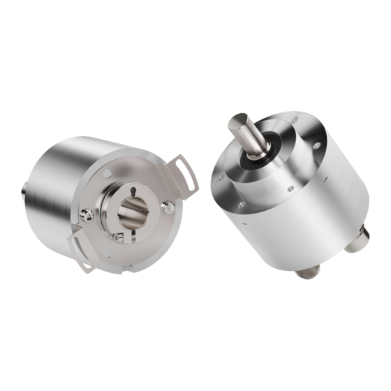
EXM58 PT
EXO58 PT
• EXM58 up to 30-bit multiturn encoder for standard purposes
• EXO58 up to 30-bit multiturn encoder for high end applications
• Encoder Profile Specifications V4.1 version 3.162
• RT real-time transmission & IRT isochronous real-time mode
• With Energy Harvesting Technology
• Multiple mechanical and electrical options
Suitable for the following models:
EXM58, EXM58S PT
•
EXM58C, EXM59C PT
•
EXO58, EXO58S PT
•
EXO58C, EXO59C PT
•
Lika Electronic
User's guide
•
Tel. +39 0445 806600
General Contents
Preliminary information
Safety summary
Identification
Mechanical installation
Electrical connections
Getting started
Profinet interface
Default parameters list
•
info@lika.biz
14
23
25
26
29
40
90
179
•
www.lika.biz
Advertisement
Chapters
Table of Contents

Related Manuals for Lika EXM58


Summary of Contents for Lika EXM58
-
Page 1: User's Guide
Smart encoders & actuators EXM58 PT EXO58 PT • EXM58 up to 30-bit multiturn encoder for standard purposes • EXO58 up to 30-bit multiturn encoder for high end applications • Encoder Profile Specifications V4.1 version 3.162 • RT real-time transmission & IRT isochronous real-time mode •... - Page 2 Tous droits réservés. This document and information contained herein are the property of Lika Electronic s.r.l. and shall not be reproduced in whole or in part without prior written approval of Lika Electronic s.r.l. Translation, reproduction and total or partial modification (photostat copies, film and microfilm included and any other means) are forbidden without written authorisation of Lika Electronic s.r.l.
-
Page 3: Table Of Contents
Table of contents User's guide......................................1 Table of contents...................................3 Subject Index....................................9 Table of figures.....................................11 Typographic and iconographic conventions........................13 Preliminary information................................14 Glossary of Profinet terms..............................15 List of abbreviations..................................20 References.......................................22 1 Safety summary........................... 23 1.1 Safety....................................23 1.2 Electrical safety................................23 1.3 Mechanical safety................................24 2 Identification............................25 3 Mechanical installation........................ - Page 4 5.7.5 Enabling the encoder............................86 5.7.6 Setting and activating the preset value....................89 6 Profinet interface..........................90 6.1 A brief introduction to Profinet..........................90 6.2 Profinet encoders from Lika Electronic......................90 6.2.1 Overview of the encoder profiles.........................92 6.3 Application Class definition.............................92 6.3.1 Application Class 3.............................92 6.3.2 Application Class 4.............................92...
- Page 5 G1_XIST2..................................101 G1_XIST3..................................102 STW2_ENC................................102 Control by PLC..............................102 Controller Sign-Of-Life..........................103 ZSW2_ENC................................103 Control requested.............................103 Encoder Sign-Of-Life............................104 G1_STW..................................104 Home position mode............................104 Request set/shift of home position......................104 Request absolute value cyclically......................106 Activate parking sensor..........................106 Acknowledging a sensor error........................107 G1_ZSW..................................107 Requirement of error acknowledge detected..................107 Set/shift of home position executed......................107 Transmit absolute value cyclically......................107 Parking sensor active............................107 Sensor error.................................107...
- Page 6 Operating status..............................119 Faults..................................119 Supported faults...............................119 Warnings................................119 Supported warnings............................119 Encoder profile version..........................119 Operating time (not used)..........................119 Offset value.................................119 Measuring units per revolution........................119 Total measuring range in measuring units....................119 Velocity measuring unit..........................119 Operating status table values........................119 Table of faults...............................120 Table of supported faults.........................120 9.5 Record Data Object 0xBF00: user parameter data..................121 Code sequence..............................121...
- Page 7 0x1002 | Parametrization error.........................135 10.4 LEDs indication................................136 10.5 States...................................137 SD1 | Normal operation..........................137 SD2 | Error acknowledgement........................137 SD3 | Error................................137 SD4 | Reference value in G1_XIST2......................137 SD5 | Wait for reference marks........................137 SD7 | Set / shift home position........................137 SD10 | Wait for measured value........................137 SD11 | Measured value in XIST2........................137 SD12 | Parking..............................137 10.6 Transitions..................................138...
- Page 8 14.2 Monitoring a variable............................160 15 Encoder state machine........................161 15.1 Normal operation diagram..........................162 15.2 Preset diagram.................................163 15.3 Parking sensor diagram............................164 15.4 Error diagram................................165 15.4.1 Acknowledgement of acknowledgeable sensor error..............165 15.4.2 Acknowledgement of not acknowledgeable sensor error............166 16 Integrated web server........................167 16.1 Web server Home page............................168 16.2 Encoder position and speed..........................169 16.2.1 Specific notes on using Internet Explorer...................170...
-
Page 9: Subject Index
Subject Index Error..................137 Error acknowledgement..........137 0x0001................133 0x0002................133 0x0003................134 Failure parking sensor..........134 0x0004................134 0x0005................134 0x0006................134 G1_STW................104 0x0007................134 G1_XIST1................99 0x0008................134 G1_XIST1 Preset control..........122 0x0009................134 G1_XIST2................101 0x000A................134 G1_XIST3................102 0x000B................135 G1_ZSW................107 0x000C................135 0x0F00................135 0x0F01................135 HARDWARE REVISION..........110 0x0F02................135 Home position mode...........104 0x0F04................135 0x0F05................135 0x1001................135 IM SUPPORTED...............110 0x1002................135 IM VERSION..............110 Index 0xAFF0..............110... - Page 10 P964 – PROFIdrive Parameter : Device Set/shift of home position executed.....107 identification.............115 SOFTWARE REVISION...........110 P965 – Encoder profile number......116 Standard Telegram 81............95 P971 – Transfer to non volatile memory....116 Standard Telegram 82............95 P975 – Encoder object identification....116 Standard Telegram 83............96 P979 –...
-
Page 11: Table Of Figures
Table of figures Figure 1 - Connectors and diagnostic LEDs....................31 Figure 2 - Installing the GSDML file......................56 Figure 3 - Selecting the GSDML file......................57 Figure 4 - GSDML file installation in progress..................57 Figure 5 - GSDML file installation completed................... 58 Figure 6 - Scrolling through Profinet families and categories..............58 Figure 7 - Adding a node to the project..................... - Page 12 Figure 45 - Acyclic parameters – Request_DB [DB1] data block............112 Figure 46 - Acyclic parameters – Response_DB [DB2] data block.............112 Figure 47 - Acyclic parameters – Acyclic Request control table............113 Figure 48 - Acyclic parameters – Finding the hardware identifier............114 Figure 49 - Setting the unsynchronized role of the IO controller............141 Figure 50 - Setting the unsynchronized role of the IO device............141 Figure 51 - Setting the synchronized role of the IO controller............143...
-
Page 13: Typographic And Iconographic Conventions
In this guide, to make it easier to understand and read the text the following typographic and iconographic conventions are used: • parameters and objects of both Lika device and interface are coloured in GREEN; alarms are coloured in RED;... -
Page 14: Preliminary Information
These programs are designed to make your own project planning, programming, communication and diagnostics with the TIA V16 development environment user-friendly and reliable. You can find them in the Lika TIA V16 CPU1500 Profinet example project.zip... -
Page 15: Glossary Of Profinet Terms
Glossary of Profinet terms PROFINET IO, like many other networking systems, has a set of unique terminology. Table below contains a few of the technical terms used in this guide to describe the PROFINET IO interface. Sometimes they also refer more specifically to the S7 programming environment. They are listed in alphabetical order. Acyclic Communications Unscheduled, demand... - Page 16 Data block In contrast to code blocks, data blocks (DB) do not contain Step 7 statements. They are used to save data, i.e. variable data which are processed by the user program. Global data blocks serve to accommodate user data which can be used by all other blocks.
- Page 17 controllers (e.g. remote IO, encoders, valve terminals, frequency converters, switches, etc.). Refer to page 90. IO Parameter Server An IO Parameter Server is a server station, usually a PC, for loading and saving the configuration data (records) of IO Devices. IO Supervisor Programming device,...
- Page 18 quicker system design and they support faster device interchange, promoting competition amongst vendors, increased choice for users and full interoperability. Provider Status The Status an IO device provides to an IO Controller with the data transferred to the Controller. Proxy A device which maps non PROFINET IO data to PROFInet.
- Page 19 3. The recipient reassembles the data packets in the correct order. 4. Faulty packets are sent again until the recipient acknowledges that they have been transferred successfully. Telegram A telegram is a rigidly defined bit stream carrying data. A telegram specifies the data length and the type of data which is sent to and from the IO controller.
-
Page 20: List Of Abbreviations
List of abbreviations Table below contains a list of abbreviations (in alphabetical order) which may be used in this guide to describe the PROFINET IO interface. Sometimes they also refer more specifically to the S7 programming environment. Application Relation Application Process Identifier C-LS Controller’s Sign-Of-Life Communication Relation... - Page 21 System function block System function Transmission Control Protocol Master Application Cycle Time MAPC...
-
Page 22: References
References 1– Profile Drive Technology. Encoder Profile. Technical Specification for PROFIBUS and PROFINET Version 4.2 March 2017 Order No: 3.162 2– Profile encoder. Technical Specification for PROFIBUS and PROFINET related to PROFIdrive Version 4.1 December 2008 Order No: 3.162 3- Profile Drive Technology. PROFIdrive Profile. Technical Specification for PROFIBUS and PROFINET Version 4.2 October 2015 Order No: 3.172 4- Profile Drive Technology PROFIdrive. -
Page 23: Safety Summary
• elsewhere in this manual violates safety standards of design, manufacture, and intended use of the equipment; Lika Electronic assumes no liability for the customer's failure to comply • with these requirements. 1.2 Electrical safety Turn OFF the power supply before connecting the device;... -
Page 24: Mechanical Safety
EXM58 • EXO58 Profinet - minimize noise by connecting the shield and/or the connector housing and/or the frame to ground. Make sure that ground is not affected by noise. The connection point to ground can be situated both on the device side and on user’s side. -
Page 25: Identification
MAC address printed on the label applied to its body. Information is listed in the delivery document too. Please always quote the order code, the serial number and the MAC address when reaching Lika Electronic for purchasing spare parts or needing assistance. For any information on the technical characteristics of the product refer to the technical catalogue. -
Page 26: Mechanical Installation
EXM58 • EXO58 Profinet Mechanical installation WARNING Installation and maintenance operations have to be carried out by qualified personnel only, with power supply disconnected. Shaft and mechanical components must be in stop. For any information on the mechanical data and the electrical characteristics of the encoder please refer to the technical catalogue. -
Page 27: Installation Using Fixing Clamps (Code Lkm386)
EXM58 • EXO58 Profinet 3.1.2 Installation using fixing clamps (code LKM386) a [mm] b [mm] c [mm] d [mm] EXM58, EXO58 50 F7 EXM58S, EXO58S 36 H7 3.1.3 Installation using a mounting bell (code PF4256) EXM58S, EXO58S encoders only MAN EXM58_EXO58 PT E 1.0... - Page 28 EXM58 • EXO58 Profinet NOTE In order to guarantee reliability over time of the encoder mechanical parts, we recommend a flexible coupling to be installed between the encoder and the motor shaft. Make sure the misalignment tolerances of the flexible coupling are met.
-
Page 29: Hollow Shaft Encoders
• insert the M4 anti-rotation pin 1 into the slot on the flange of the encoder; this secures it in place by grub screw 2, preset at Lika; • fix the collar to the encoder shaft (apply threadlocker to M2.5 screw 3). -
Page 30: Exm59C, Exo59C
EXM58 • EXO58 Profinet 3.2.2 EXM59C, EXO59C • Mount the encoder on the motor shaft using the reducing sleeve 6 (if supplied). Avoid forcing the encoder shaft; • fasten the fixing plate 4 to the rear of the motor using two M3 cylindrical head screws 5;... -
Page 31: Electrical Connections
EXM58 • EXO58 Profinet Electrical connections WARNING Power supply must be turned off before performing any electrical connection! Installation, electrical connection, and maintenance operations must be carried out by qualified personnel only, with power supply disconnected. Mechanical components must be in stop. -
Page 32: Pwr Power Supply Connector (Figure 1)
EXM58 • EXO58 Profinet 4.1 PWR Power supply connector (Figure 1) M12 4-pin male connector with A coding is used for power supply. Description +5Vdc +30Vdc n.c. 0Vdc n.c. n.c. = not connected WARNING Connect +Vdc and 0Vdc and check the power supply is correct first before connecting the communication ports. -
Page 33: Line Termination
EXM58 • EXO58 Profinet Using Ethernet several topologies of connection are supported by Profinet networks: line, tree, daisy-chain, star, … . Furthermore Profinet networks can be configured in almost any topology in the same structure. The connection of PROFINET IO field devices occurs exclusively with switches as network components. -
Page 34: Mac Address And Ip Address
Lika's EC- pre-assembled cables are fitted with shield connection to the connector ring nut in order to allow grounding through the body of the device. Lika's E- connectors have a plastic gland, thus grounding is not possible. If metal connectors are used, connect the cable shield properly as recommended by the manufacturer. -
Page 35: Diagnostic Leds (Figure 1)
EXM58 • EXO58 Profinet 4.7 Diagnostic LEDs (Figure 1) Five LEDs located in the rear of the encoder (see Figure 1) are meant to show visually the operating or fault status of the encoder and the Profinet interface. The meaning of each LED is explained in the following tables. - Page 36 EXM58 • EXO58 Profinet another device. Wrong station address assigned (but not However, the outside the permitted range). device / Slave did Actual configuration of the device / not switch to the Slave differs from the nominal data exchange mode configuration.
-
Page 37: Led State Definition
EXM58 • EXO58 Profinet Ethernet frames through port 2 P2. L/A Link/Activity LED for port 1 P1 (green / yellow) It shows the state and the activity of the physical link (port 1 P1). Description Meaning The device has no link to the Ethernet, the link through port 1 P1 is not active. -
Page 38: States
EXM58 • EXO58 Profinet followed by "OFF" for 50 ms. The LED turns ON and OFF in irregular intervals to indicate low Ethernet activity. 4.9 States Here follows the list of the Profinet states. ERROR state There is at least one serious network error. The Read Process Data shall be regarded as not valid. -
Page 39: Operate State
EXM58 • EXO58 Profinet OPERATE state The I/O connection is established and valid I/O data is exchanged between the Controller and the Device. PROCESS_ACTIVE state The network Process Data channel is active and error free. Perform normal data handling. SETUP state The setup of the device is in progress. -
Page 40: Getting Started
GSDML file, see on page 56 ff; • insert the Lika module and the type of telegram in the PROFINET-IO • system, see on page 59 ff; set the device name, see on page 64 ff; at delivery the device name is •... -
Page 41: Reading The Position
• instance, if the Standard Telegram 83 is installed, use the Telegram 0x53 table available in the project example provided by Lika, see on page 96; see also the G1_XIST1 parameter on page 99, the G1_XIST2 parameter on page 101, and the G1_XIST3 parameter on page 102). -
Page 42: Setting And Activating The Preset Via Tia Portal And The Example Project
To set and activate the preset, please refer also to the “9.2 Record Data Objects” section on page 110. Refer also to the Preset EXM58 Profinet encoder Lika.mp4 video. To set and activate the preset via TIA PORTAL development environment we... - Page 43 EXM58 • EXO58 Profinet check the hardware identifier of the installed encoder module; to do this • go to the Device view and select the Parameter Access Point. Then enter the System constants tab in the Inspector window: in the Hardware identifier column you will find the address of the installed encoder module (“264”...
- Page 44 EXM58 • EXO58 Profinet the Acyclic request watch table will be displayed; • in the Acyclic request table check and set -if required- the following • items: ◦ WRREC_Data.ID: it is the hardware identifier of the encoder's hardware module; please check it matches the one of your encoder (“264”...
- Page 45 EXM58 • EXO58 Profinet ◦ Request_DB.Parameter_number_01: it is the number of the parameter to access; it is “65000” for the preset value, see the P65000 – Preset value parameter on page 118; ◦ Request_DB.Value: enter here the preset value you want to set;...
- Page 46 EXM58 • EXO58 Profinet You need to activate the preset value through the set telegram now. To do this proceed as follows: in the Project tree on the left select the Telegram 0x53 item under • Watch and force tables; the Telegram 0x53 watch table will be displayed;...
- Page 47 EXM58 • EXO58 Profinet the encoder replies by forcing high the Set/shift of home position • executed bit 12 in the G1_ZSW status word, see on page 107; see the G1_ZSW.12 item as well as the G1_XIST1 and G1_XIST2 items;...
- Page 48 EXM58 • EXO58 Profinet the Set/shift of home position executed bit 12 in the G1_ZSW status • word is set back to 0, see on page 107; see the G1_ZSW.12 item. WARNING It is mandatory to set the G1_STW.12 item back to 0 to avoid the preset value to be entered endlessly.
-
Page 49: Configuring The Encoder With Siemens Tia Portal V16
If the encoder is used as a TO Technology Object, please refer to the “5.7 TO Technology Objects” section on page 78. Please see the example projects available in the Lika TIA V16 CPU1500 Profinet example project.zip compressed file. 5.2.1 About TIA Portal TIA Portal stands for Totally Integrated Automation Portal. -
Page 50: Project Overview
EXM58 • EXO58 Profinet 5.2.2 Project overview 1. Title bar: the name of the project is displayed in the title bar. 2. Menu bar: the menu bar contains all the commands that you require for your work. 3. Toolbar: the toolbar provides you with buttons for commands you will use frequently. - Page 51 53. In the Figure above the SIEMENS PLC CPU 1512SP-1 PN is the Master device and is connected to Lika's EXM5XX-13-14 encoder, i.e. the Slave device, through the PLC_1.PROFINET IO-... connection.
-
Page 52: Device View
EXM58 • EXO58 Profinet selecting objects from a library or from the hardware catalog • searching for and replacing objects in the project • dragging predefined objects to the work area • The task cards available can be found in a bar on the right-hand side of the screen. -
Page 53: Topology View
EXM58 • EXO58 Profinet Multiple controllers, peripherals, HMI devices, SCADA stations, PC • stations, and drives possible in a single project Procedure for integrating AS-i devices identical to PROFIBUS/PROFINET • Zoom and page navigation • Copying/pasting entire stations, incl. configuration, or individual •... -
Page 54: Installing The Encoder Under Tia Portal Environment
XXXXXXXX is the release date of the file in a 8-digit format encompassing information about year (4 digits), month (2 digits), and day (2 digits): 20230417 is the first GSDML file released by Lika Electronic for EXM58 & EXO58 Profinet encoders. Enter Lika's web site www.lika.biz to get the GSDML file. - Page 55 EXM58 • EXO58 Profinet Version structure of GSDML files The GSDML file structure is in compliance with the ISO 15745 "Open Systems Application Integration Framework" and is oriented on the defined profile of a field device via the following model: GSDML- V2.35-...
-
Page 56: Installing The Gsdml File
EXM58 • EXO58 Profinet 5.5.2 Installing the GSDML file In the menu bar of the main window, press Options and then Manage general station description files (GSD) command. Figure 2 - Installing the GSDML file MAN EXM58_EXO58 PT E 1.0... -
Page 57: Figure 3 - Selecting The Gsdml File
EXM58 • EXO58 Profinet The Manage general station description files dialog box will appear. Press the SOURCE PATH button to choose the folder where the GSDML file is located. Please make sure that the bitmap file representing the encoder is located in the same folder as the GSDML file. -
Page 58: Figure 5 - Gsdml File Installation Completed
Now scroll through the directory tree in the Hardware Catalog pane of the main window (task cards) and select the path Catalog \ Other Field devices \ PROFINET IO \ Encoders \ Lika Electronic: the LIKA EXM-EXO family can be found inside the folder. The installation modules are contained inside the directories MULTITURN (for multiturn version encoders) and SINGLETURN (for singleturn version encoders). -
Page 59: Adding A Node To The Project
In the right pane, open the Hardware catalog task card to display the field devices integrated into TIA Portal via the Profinet file (GSDML file); select the LIKA EXM-EXO directory; drag the required module LIKA EXM5xx-13-14 to the Network view and drop it next to the PLC module. Then assign the module to the network. -
Page 60: Establishing The Bus Connection
EXM58 • EXO58 Profinet 5.5.4 Establishing the bus connection As soon as the device has been inserted into the project, the bus connection with the PLC can be established in the Network view. A PROFINET IO system is comprised of a PROFINET IO controller and its assigned PROFINET IO devices. -
Page 61: Inserting The Telegrams
For instance, we need to install the Standard Telegram 83. To do this switch to the Device view first, then select the desired Telegram available for the module LIKA EXM5xx-13-14 under the SUBMODULES directory in the Catalog task card. Drag and drop the STANDARD TELEGRAM 83 submodule onto the table area, as shown in the Figure. -
Page 62: Device Name And Ip Address At Delivery
NOTE An IO Device does not have a device name when delivered. By default, the device name of Lika's Profinet encoders is set to a blank string. The device names must satisfy DNS (Domain Name System) conventions: Names are limited to a total of 127 characters (letters, numbers, dashes •... - Page 63 EXM58 • EXO58 Profinet Steps for system start-up Controller Device Checking of device name Assignment of IP address Connection establishment Data exchange Start-up response IO CONTROLLER IO DEVICE Event: power supply on or Call Event: power supply on or loading of configuration...
-
Page 64: Setting The Device Name And The Ip Address In The Project
EXM58 • EXO58 Profinet 5.5.7 Setting the device name and the IP address in the project As stated, to completely establish the connection, you have to set and assign the Profinet device name and the IP address to the Slave device. First of all you need to set the Profinet device name and the IP address in the project. -
Page 65: Compiling And Transferring The Project
EXM58 • EXO58 Profinet Enter the PROFINET group box and set a desired name in the PROFINET device name field or select the Generate PROFINET device name automatically check box if you want the name to be generated automatically by TIA. -
Page 66: Assigning The Device Name And The Ip Address To The Device
EXM58 • EXO58 Profinet Figure 13 - Downloading the project 5.5.9 Assigning the device name and the IP address to the device After having set the Profinet device name and the IP address to the device in the project, you must assign them to your real device in the network. -
Page 67: Figure 15 - Profinet Device Name
EXM58 • EXO58 Profinet The Assign PROFINET device name dialog box will be displayed. In the PROFINET device name field the device name will be automatically displayed. It cannot be changed. If you want a different name to be assigned, you must repeat the procedure by setting the device name again in the Ethernet addresses menu option (see the “5.5.7 Setting the device name and... -
Page 68: Figure 16 - Assigning The Device Name
EXM58 • EXO58 Profinet As soon as the search operation is carried out, the list of the accessible devices in the network will appear in the table, as shown in the Figure below. Select the device you want the Profinet device name to be assigned to and then press the ASSIGN NAME button to complete the pairing operation. -
Page 69: Module Parameters
EXM58 • EXO58 Profinet 5.5.10 Module parameters Press the Device view changeover switch in the Hardware and network editor to enter the Device view working area, then select the device you need to configure in the drop-down box on the top left of the graphic area. Select the Module Access Point field in Device view. -
Page 70: Figure 18 - Description / Help Message (Tooltip)
EXM58 • EXO58 Profinet Please note that a description / help message (tooltip) appears on the display when you move the cursor over the items listed in the table. Figure 18 - Description / help message (tooltip) For a comprehensive description of the parameters and how to set them properly refer to the specific explanation in the “9.5 Record Data Object 0xBF00:... -
Page 71: Establishing An Online Connection (Online Mode)
EXM58 • EXO58 Profinet 5.5.11 Establishing an online connection (Online mode) Figure 19 - Establishing an online connection In online mode, there is an online connection between the PLC and one or more devices. An online connection between the PLC and the device is required, for example, for the following tasks: using the Control Table;... -
Page 72: Figure 20 - Online Connection Established
EXM58 • EXO58 Profinet If the device has already been connected online, the online connection is • automatically established using the previously specified connection path. If there was no previous connection, the Go online dialog opens. • Select the connection path: •... -
Page 73: Closing An Online Connection
EXM58 • EXO58 Profinet will find more information on the error in Diagnostics in the Inspector window. 4. Operating mode symbols or diagnostics symbols for the stations connected online and their underlying objects are shown in the Project Tree. A comparison of the online and offline status is also made automatically. -
Page 74: Resetting The Parameters To The Default Factory Values
Default values are provided to each parameter of the device and are preset at the factory by Lika Electronic engineers. For the complete list of machine data and relevant default parameters, please refer to page 179. The first time you install the encoder, it will operate using the default values. -
Page 75: Figure 21 - Restoring Default Values
NOTE The complete list of machine data and relevant default parameters preset by Lika Electronic engineers is available on page 179. When you need to restore the default values proceed as follows. Enter the Device view working area, select the device you need to configure in the drop-down box on the top left of the graphic area, right-click on the image of the module and select the Online &... -
Page 76: Figure 22 - Going Online
EXM58 • EXO58 Profinet To get started with the diagnostic functions you must go online. To do this you must press the Go online command in the Online menu bar (see also the “5.5.11 Establishing an online connection (Online mode)” section on page 71). -
Page 77: Figure 24 - Confirming The Reset To Factory Settings
EXM58 • EXO58 Profinet Next to the MAC address item in the Reset to factory settings graphic area enter the MAC address of the encoder you need to reset (it is written on the encoder label) and then press the RESET button to confirm. -
Page 78: To Technology Objects
EXM58 • EXO58 Profinet When the operation is carried out, if you browse the network to find the accessible devices, you will see the value 0.0.0.0 under the IP address item and three dashes under the PROFINET device name item, they are followed by the message “No device name assigned”. -
Page 79: Properties Of A Technology Object (To)
EXM58 • EXO58 Profinet 5.7.1 Properties of a technology object (TO) A technology object (TO) for motion control in the SIMATIC has the following properties: The technology object represents a software object in the controller. • The technology object represents the mechanical components. -
Page 80: Figure 27 - Adding A New Technology Object
EXM58 • EXO58 Profinet When you need to add a new technology object, click Add new object under the Technology objects item in the project tree: the Add new object dialog box will be displayed. Figure 27 - Adding a new technology object In the Add new object dialog box, select the entry TO_ExternalEncoder under the Motion Control list. -
Page 81: Figure 29 - Setting The To Basic Parameters
Under Hardware interface set both the Encoder parameters and the Data exchange parameters. Select the telegrams to be used and set the singleturn resolution and the number of revolutions. In the example an EXM58-13-14- PT4-... encoder is to be connected as TO. -
Page 82: Figure 31 - Encoder Area With Configured To
EXM58 • EXO58 Profinet As soon as the parameters are set, some green ticks will appear in the lateral bar to indicate the proper configuration. When the TO is configured, the Encoder page will appear as in the following view:... -
Page 83: Adding Additional Data Blocks And Function Blocks
EXM58 • EXO58 Profinet 5.7.3 Adding additional data blocks and function blocks Some data blocks and function blocks are added automatically when you install the new encoder object. Figure 33 - Implemented functions MAN EXM58_EXO58 PT E 1.0 Getting started... -
Page 84: Figure 34 - Data Blocks And Function Blocks
Figure 34 - Data blocks and function blocks They can be found already created in the projects that are supplied by Lika Electronic. See the watch table in the Figure below. Refer to the Lika TIA V16 CPU1500 Profinet example project.zip compressed file contained in the SW EXM58_EXO58 PT.zip file. -
Page 85: Downloading The Project And Going Online
EXM58 • EXO58 Profinet 5.7.4 Downloading the project and going online After the project has been successfully completed, the controller can be selected and the created program can be downloaded. To do this press the DOWNLOAD TO DEVICE button in the toolbar. -
Page 86: Enabling The Encoder
EXM58 • EXO58 Profinet After the download is carried out, you can go online by pressing the GO ONLINE button in the toolbar. Once the online connection to the controller is established, you can enter the diagnostic functions. To do this select the Technology Object and then the Diagnostics item in the Project tree. -
Page 87: Figure 39 - To Watch And Force Tables
EXM58 • EXO58 Profinet To enable the encoder select the Watch and force tables and then the Telegram 0x53 (Telegram 83) item in the Project tree. The Telegram 83 watch table will be displayed. Figure 39 - TO Watch and force tables Select the MC_POWER_DB.Enable function, right-click on the item in the... -
Page 88: Figure 41 - To Encoder Enabled
EXM58 • EXO58 Profinet In the Status and error bits pane check that the encoder is enabled now. Figure 41 - TO encoder enabled MAN EXM58_EXO58 PT E 1.0 Getting started 88 of 180... -
Page 89: Setting And Activating The Preset Value
EXM58 • EXO58 Profinet 5.7.6 Setting and activating the preset value NOTE We suggest activating the preset value when the encoder is in stop. Preset function is meant to assign a desired value to a known physical position of the system. The chosen physical position will get the value set next to this index and all the previous and following mechanical positions will get a value according to it. -
Page 90: Profinet Interface
XML language, thus it is called GSDML file, see on page 54. 6.2 Profinet encoders from Lika Electronic PROFINET encoders from Lika Electronic fully comply with the specifications of the encoder profile V4.1 version 3.162, the encoder profile is based on the PROFIdrive profile. - Page 91 • support for Alarm Mechanism. • Among the parameters available in the Profinet encoders from Lika Electronic: code sequence, scaling function, preset (Class 4 functionalities), position readout, offset value, velocity value, velocity measuring unit, acyclic Error Data communication, and diagnostic information.
-
Page 92: Overview Of The Encoder Profiles
Encoder with scaling, preset, isochronous mode, and base mode parameter access. A Class 4 configured encoder fully supports all functionalities according to the encoder profile 4.1. Lika Electronic encoders fulfil the requirements of CLASS 4 MAN EXM58_EXO58 PT E 1.0 Profinet interface... -
Page 93: Encoder Object Model
EXM58 • EXO58 Profinet 6.4 Encoder Object model The Figure shows the general Encoder Object (EO) architecture. The central element of the EO is the Process Control Task where the measurements are made and the results are calculated. The properties of the EO and the Process Control task are represented and controlled by parameters. -
Page 94: Encoder Object Architecture
EXM58 • EXO58 Profinet 6.5 Encoder object architecture The Figure shows the general architecture and the mapping of the Encoder Object (EO) architectural elements to Communication Objects of the Peripheral Device for PROFINET IO. Generally with PROFINET IO the EO is mapped exactly to one Module/Slot. -
Page 95: Profinet Io Data Description
EXM58 • EXO58 Profinet PROFINET IO data description 7.1 Telegrams A telegram is a rigidly defined bit stream carrying data and an aggregation of one or multiple Signals. In each telegram the data length and the type of data which is sent to and from the IO controller is specified. PROFINET interface devices communicate and stay in sync by sending telegrams each other. -
Page 96: Standard Telegram 83
EXM58 • EXO58 Profinet 7.1.3 Standard Telegram 83 The Standard Telegram 83 uses 4 bytes to output data from the IO controller to the encoder and 16 bytes to input data from the encoder to the IO controller. Output data CONTROLLER => DEVICE... -
Page 97: Cyclic Data Exchange - Std Signals
EXM58 • EXO58 Profinet Cyclic Data Exchange – Std signals IO data is transferred via the Cyclic Data Exchange, i.e. cyclically, between the EO and other devices (controller, supervisor, device). A series of standard signals is defined to configure the IO data. In the following table the standard signals are summarily described. - Page 98 EXM58 • EXO58 Profinet MAN EXM58_EXO58 PT E 1.0 Cyclic Data Exchange – Std signals 98 of 180...
-
Page 99: List Of The Available Standard Signals
(see on page 126 and ff). EXAMPLE Scaling We install the EXM58-13-14-... encoder with 27-bit resolution. The function control parameter is disabled = 0, so G1_XIST1 provides the current position value in a 32 bit format: position values are from 0 to 4,294,967,295. - Page 100 EXM58 • EXO58 Profinet EXAMPLE Here follows a format example. EXM58-13-14 27-bit absolute multiturn encoder, 13-bit singleturn resolution (8,192 counts per revolution), 14-bit multiturn resolution (16,384 revolutions) M = Multiturn value, number of revolutions = Singleturn value, number of counts per revolution...
-
Page 101: G1_Xist2
EXM58 • EXO58 Profinet G1_XIST2 [Unsigned, 32 bits] It is defined as Sensor 1 current position value 2. By default this signal is the current (real) absolute position of the encoder expressed in binary notation yet it has a different meaning if an error is active. -
Page 102: G1_Xist3
EXM58 • EXO58 Profinet G1_XIST3 [Unsigned, 64 bits] It is defined as Sensor 1 current position value 3. This 64-bit position value is intended to support the encoders having a measuring length which exceeds 32 bits. G1_XIST3 has the following format: binary format;... -
Page 103: Controller Sign-Of-Life
EXM58 • EXO58 Profinet If the Compatibility Mode parameter is disabled (see on page 125: 1 = Compatibility with Encoder Profile V4.1), then the bit 10 Control by PLC is checked. So the control word G1_STW and the setpoints are checked only if the bit Control by PLC is set. -
Page 104: Encoder Sign-Of-Life
EXM58 • EXO58 Profinet Control by the automation system is not No Control possible, only possible at the device or by requested another interface. Encoder Sign-Of-Life Bits 12 … 15 For complete information on the Sign-Of-Life mechanism refer to the PROFIdrive Technical Specification document. - Page 105 EXM58 • EXO58 Profinet The preset function is controlled by bits 11 and 12 in this Sensor 1 control word G1_STW and acknowledged by the bit 12 Set/shift of home position executed in the sensor status word G1_ZSW. The preset value is 0 by default and can be set by an acyclic data exchange parameter defined in the parameters section (see P65000 –...
-
Page 106: Request Absolute Value Cyclically
EXM58 • EXO58 Profinet Master now. The encoder will end the preset cycle by clearing the bit 12 Set/shift of home position executed in the sensor status word G1_ZSW. The internal offset value will be shifted according to the transferred preset value. The new offset value is securely stored in case of voltage breakdown and uploaded again at each power on. -
Page 107: Acknowledging A Sensor Error
EXM58 • EXO58 Profinet is running is not allowed and will result in a sensor interface error (error 0x0003 | Failure parking code sensor in G1_XIST2, see on page 133). See also “15.3 Parking sensor diagram” on page 164. Acknowledging a sensor error... -
Page 108: Nist_A
EXM58 • EXO58 Profinet NIST_A [Signed, 16 bits] It is defined as current velocity value A expressed in a 16 bit format. Velocity value is calculated every 100 ms. Velocity measuring unit Refer also to the parameter on page 128. -
Page 109: Acyclic Data Exchange
EXM58 • EXO58 Profinet Acyclic Data Exchange In addition to the Cyclic Data Exchange (see the “Cyclic Data Exchange – Std signals” section on page 97), the Acyclic Data Exchange gives the possibility to read and write parameters over the non real time channel. -
Page 110: Index 0Xaff0: Identification & Maintenance (I&M) Functions
EXM58 • EXO58 Profinet 9.1 Index 0xAFF0: Identification & Maintenance (I&M) functions Profinet encoders from Lika Electronic only implement I&M 0 Module (IM0). IM0 is accessible with record 0xAFF0 and provides general information on the device such as vendor ID, order ID, serial number, etc. -
Page 111: How To Access (Read And Write) Acyclic Parameters
Index (Record Data Object) 0xB02E parameters must be accessed for reading and writing purposes only by using the program described hereafter. Please refer also to the example projects provided by Lika. See the Lika TIA V16 CPU1500 Profinet example project.zip compressed file contained in the SW EXM58_EXO58 PT.zip file. -
Page 112: Figure 44 - Acyclic Parameters - Adding A New Block
EXM58 • EXO58 Profinet The program shown above must be inserted into a cyclic Organization Block. It is possible to use the main OB1 organization block or add a new organization block according to the user's needs, as in the example (OB123). -
Page 113: Figure 47 - Acyclic Parameters - Acyclic Request Control Table
EXM58 • EXO58 Profinet Their addresses are set in the Record field of WRREC_DB and RDREC_DB function blocks respectively (see Network 2 and Network 5 in the main program shown in Figure 43). A boolean Request R/W param single variable at address %M0.0 is used as a flag to start the parameter read/write process. -
Page 114: Figure 48 - Acyclic Parameters - Finding The Hardware Identifier
EXM58 • EXO58 Profinet To know the hardware identifier of the installed encoder module, go to the Device view and select the Parameter Access Point. Then enter the System constants tab in the Inspector window: in the Hardware identifier column you will find the address of the installed encoder module (“264”... -
Page 115: Record Data Object 0Xb02E: Supported Profidrive Specific Parameters
EXM58 • EXO58 Profinet Parameter_number_01 contains the number of the parameter to access (it is “65000” for the preset value in the example, see the P65000 – Preset value parameter on page 118). SubIndex contains the sub-index of the desired item, if required. -
Page 116: P965 - Encoder Profile Number
EXM58 • EXO58 Profinet NOTE Software version, Software year, and Software day and month are expressed in decimal notation. For example: Software version = xxyy (decimal). Version 2.1 results in 0201 decimal. P965 – Encoder profile number [Octet string 2, RO] Parameter P965 –... -
Page 117: P979 - Sensor Format
EXM58 • EXO58 Profinet Application Class 4 supported) Drive object ID (DO ID) 0x01 NOTE Software version, Software year, and Software day and month are expressed in decimal notation. For example: Software version = xxyy (decimal). Version 2.1 results in 0201 decimal. -
Page 118: P61001 - Ip Of Station
EXM58 • EXO58 Profinet P61001 – IP of station [Unsigned32, RO] Index Sub Meaning Value Access 61001 IP address assigned to the encoder variable 9.4 Record Data Object 0xB02E: supported encoder specific parameters P65000 – Preset value [Unsigned32, RW] Preset mode absolute Preset function is meant to assign a desired value to a known physical position of the system. -
Page 119: P65001 - Operating Status
EXM58 • EXO58 Profinet P65001 – Operating status [Array , unsigned32, RO] [0 ... 11] This parameter has a read only structure. It provides information on the operating status of the encoder and on the current status of the Faults and Warnings. -
Page 120: Table Of Faults
EXM58 • EXO58 Profinet 7 … 27 Reserved for future use by the profile 28 … 31 Reserved to the encoder manufacturer Table of faults Meaning Position error 1 … 3 Not used Commissioning diagnostics Memory error 6 … 31 Not used For complete information refer to the “10.2.1 Use of the ChannelErrorType”... -
Page 121: Record Data Object 0Xbf00: User Parameter Data
EXM58 • EXO58 Profinet 9.5 Record Data Object 0xBF00: user parameter data The 31-byte user parameter data listed in the table below is sent to the encoder at each start-up using the record data object 0xBF00. These parameters are available in the Module parameters tabbed page under TIA Portal, see the “5.5.10 Module parameters“... -
Page 122: Class 4 Functionality
EXM58 • EXO58 Profinet Absolute position value increasing (count up information) when the shaft rotates counter-clockwise (viewed from shaft end) Default = 0 = CW (min. = 0, max. = 1) WARNING Changing this value causes also the position calculated by the controller to be necessarily affected. -
Page 123: Scaling Function Control
4,294,967,295; integrated position values (between 2 and 2 for EXM58- 13-14-...; between 2 and 2 for EXO58-18-00-...; between 2 and 2 EXM58-18-12-... and EXO58-16-14-...) are retained as long as the power supply MAN EXM58_EXO58 PT E 1.0 Acyclic Data Exchange 123 of 180... -
Page 124: Alarm Channel Control
126 and ff). EXAMPLE Scaling We install the EXM58-13-14 encoder with 27-bit resolution. The function control parameter is disabled = 0, so G1_XIST1 provides the current position value in a 32 bit format: position values are from 0 to 4,294,967,295. -
Page 125: Compatibility Mode
EXM58 • EXO58 Profinet Compatibility Mode This parameter defines whether the encoder has to run in a mode compatible with Version 3.1 of the Encoder Profile. See the table below for an overview of the functions affected when the compatibility mode is enabled. -
Page 126: Scaling Function Parameters
EXM58 • EXO58 Profinet Scaling function parameters Using the scaling function parameters the absolute position value of the encoder is converted by the software in order to customize the resolution of the encoder according to needs. The scaling parameters will only be activated if the... -
Page 127: Total Measuring Range
Default = 134,217,728 (min. = 1, max. = 134,217,728) for EXM58-13-14 262,144 (min. = 1, max. = 262,144) for EXO58-18-00 1,073,741,824 (min. = 1, max. = 1,073,741,824) for EXM58-18-12 and EXO58-16-14 NOTE There is no functionality of this parameter if the Scaling function control parameter is disabled. -
Page 128: Maximum Tolerated Failures Of Master Sign-Of-Life
EXM58 • EXO58 Profinet NOTE When you change the value next to this parameter, then you are required to enter a new preset. Maximum tolerated failures of Master Sign-Of-Life This parameter sets the number of allowed failures of the Master’s sign of life. -
Page 129: Red Zone
EXM58 • EXO58 Profinet 9.6 "Red Zone" The so-called “Red Zone” problem occurs when the Number of revolutions (i.e. Total measuring range Measuring units / Revolution) is not a power of When this problem arises, the device must operate within the “red zone” for a certain number of positions. - Page 130 EXM58 • EXO58 Profinet It results from this: Number of revolutions = 6,748 = it is NOT a power of 2 • This can be proved easily: Overall physical resolution 1,073,741,824 = 2.427... Overall set resolution 442,236,928 It follows that for 189,267,968 positions (1,073,741,824 – 442,236,928 * 2 = 189,267,968), i.e.
-
Page 131: Diagnostics And Alarms
EXM58 • EXO58 Profinet 10 Diagnostics and Alarms Diagnostics data is always transferred acyclically using Record Data communication over the non real time channel. A PN-IO controller can request diagnostic data from the PN-IO device using RDO (Record Data Object) services. -
Page 132: Acyclic Diagnosis Parameter P65001 - Operating Status
EXM58 • EXO58 Profinet 10.1 Acyclic diagnosis parameter P65001 – Operating status With the P65001 – Operating status Acyclic parameter the current status of the Encoder Faults and Warnings as well as the support of the individual Fault and Warning bits can be read from the encoder. For detailed information on the P65001 –... -
Page 133: Use Of The Channelerrortype
EXM58 • EXO58 Profinet 10.2.1 Use of the ChannelErrorType For Profinet the encoder faults and warnings are mapped to the ChannelErrorTypes defined in the PROFIdrive profile, see the tables below. This means that there are no specific codes defined for stand-alone encoders and a PROFINET controller will interpret the errors from an encoder in the same ways as an error coming from a drive. -
Page 134: 0X0003 | Failure Parking Sensor
EXM58 • EXO58 Profinet 0x0003 | Failure parking sensor SD12 | Parking Error because transition to is not possible. This may be e.g. because the drive is currently running (state S4 operation) and the motor measurement system is forced to parking. -
Page 135: 0X000B | Abort Absolute Value Transmission
EXM58 • EXO58 Profinet 0x000B | Abort absolute value transmission Reserved. 0x000C … 0x0F00 | reserved 0x000C … 0x0F00 0x0F01 | Command not supported Error because optional function (e.g. shift/preset home position) is not supported. 0x0F02 | Master’s sign of life fault The number of permissible failures of the Master’s sign of life was exceeded. -
Page 136: Leds Indication
EXM58 • EXO58 Profinet NOTE 2 In Clock cycle synchronous applications the encoder additionally indicates the 0x0F04 | Synchronization fault error described by error code by setting the encoder’s Sign-Of-Life to zero. 10.4 LEDs indication Errors are further indicated through LEDs. Five LEDs located in the rear of the encoder (see Figure 1) are designed to show visually the operating or fault status of the encoder and the Profinet interface. -
Page 137: States
EXM58 • EXO58 Profinet 10.5 States State | Name Action Explanation Identification / Status information SD1 | Normal operation None The position feedback interface operates G1_ZSW bit 0-7 = 0000 0000b, normally. G1_ZSW bit 10-15 = 00x000b Transmission of XIST2 in G1_XIST2 is possible if requested by G1_STW bit 13=1. -
Page 138: Transitions
EXM58 • EXO58 Profinet 10.6 Transitions Transition Number Source State Destination State Condition SD2 | Error SD1 | Normal G1_STW bit 15 = 0 acknowledgement operation and error removed SD4 | Reference SD1 | Normal G1_STW bit 4-6 = value in G1_XIST2... -
Page 139: Td16
EXM58 • EXO58 Profinet Transition Number Source State Destination State Condition TD16 Every state SD12 | Parking G1_STW bit 14 = 1 additional condition, when SD13, SD14 are implemented: or when (G1_XIST1 is invalid and no error is occurred or present) -
Page 140: Real Time Class Communication
EXM58 • EXO58 Profinet 11 Real time class communication Within PROFINET IO, process data and alarms are always transmitted in real time. Real-Time for PROFINET (RT) is based on the definitions of IEEE and IEC for high-performance data exchange of I/O data. RT communication constitutes the basis for data exchange in PROFINET IO. -
Page 141: Figure 49 - Setting The Unsynchronized Role Of The Io Controller
EXM58 • EXO58 Profinet 2. select the IO controller (PLC_1) in the table area; 3. in the Properties inspector window, General tab, press the Synchronization menu option; 4. enter the Synchronization group box and set the Unsynchronized option through the drop-down list box in the Synchronization role item. -
Page 142: Real-Time Class 3 (Irt_Top) (Rt3)
EXM58 • EXO58 Profinet 2. if needed, select the device you need to configure in the drop-down box on the top left of the graphic area; 3. select the encoder; 4. in the Properties inspector window, General tab, press the Real time settings menu option;... -
Page 143: Figure 51 - Setting The Synchronized Role Of The Io Controller
EXM58 • EXO58 Profinet Figure 51 - Setting the synchronized role of the IO controller IO device (Figure 52) 1. Press the Device view changeover switch in the Hardware and network editor to enter the Device overview working area; Figure 52 - Setting the synchronized role of the IO device 2. -
Page 144: Figure 53 - Setting The Isochronous Mode For The Telegram
EXM58 • EXO58 Profinet 6. now in the Device overview working area select the telegram you have installed (Standard Telegram 83 in Figure 53); Figure 53 - Setting the isochronous mode for the telegram 7. in the Properties inspector window, General tab, press the I/O addresses menu option;... -
Page 145: Figure 55 - I/O Addresses Set
EXM58 • EXO58 Profinet 10. select the Synchronous Cycle [OB61] organization block; if it is not present in the menu press the ADD NEW button and select it in the Add new block page that appears; 11. press the green tick button to confirm and close the menu;... -
Page 146: Ob61
EXM58 • EXO58 Profinet 11.4 OB61 WARNING Use of OBs requires both in-depth skills and specific expertise in TIA PORTAL programming environment. For detailed information please consult the TIA PORTAL Programmer's handbook and documentation. Organization blocks (OBs) form the interface between the CPU operating system and the user program. -
Page 147: Pip (Process Image Partition)
EXM58 • EXO58 Profinet 11.5 PIP (Process Image Partition) WARNING Use of PIPs requires both in-depth skills and specific expertise in TIA PORTAL programming environment. For detailed information please consult the TI PORTAL Programmer's handbook and documentation. 11.5.1 Consistency PIPs (Process Image Partitions) are used to update the distributed IO device synchronously with the constant bus cycle time clock. -
Page 148: Encoder Replacement Using Lldp
EXM58 • EXO58 Profinet 12 Encoder replacement using LLDP LLDP (Link Layer Discovery Protocol) is a Layer 2 protocol that is used to detect the closest neighbours in the network. It enables a device to send information about itself and to save information received from neighbouring devices, i.e. it provides the option of communicating data between neighbouring devices (e.g. - Page 149 EXM58 • EXO58 Profinet NOTE When you replace a device, make sure that the PROFINET cable is then inserted into the correct port as it is configured in TIA Portal. Otherwise, the system will not run. MAN EXM58_EXO58 PT E 1.0...
-
Page 150: Media Redundancy Protocol (Mrp)
EXM58 • EXO58 Profinet 13 Media Redundancy Protocol (MRP) MRP (Media Redundancy Protocol) is a redundancy protocol supported by all Profinet capable devices that will allow a network to be configured in a ring topology. It is standardized by the International Electrotechnical Commission as IEC 62439-2. -
Page 151: Setting Mrp Roles
EXM58 • EXO58 Profinet 13.1 Setting MRP roles Within an MRP ring, each device must be assigned a role. One device will be the MRP Manager (MRM) and will be responsible for sending out test frames to detect for a network failure and for blocking network traffic on one port (except for the test frames) to prevent a network loop. -
Page 152: Figure 61 - Setting The Encoder As The Mrc
EXM58 • EXO58 Profinet We do the same for the encoder: it must be set as a client. Go to the Device view for the encoder and look at the properties of the network interface. Under Advanced Options, look for Media redundancy item. -
Page 153: Configuring The Network Topology
EXM58 • EXO58 Profinet 13.2 Configuring the network topology To configure the network topology proceed as follows. Navigate to the Topology view tab of the Devices and Networks view. Configure the topology to create a ring by connecting the ports, for instance as shown in the Figure. -
Page 154: Interconnecting The Ports In The Inspector Window
EXM58 • EXO58 Profinet 13.3 Interconnecting the ports in the Inspector window To interconnect the ports, follow these steps. 1. In the Device view tab or Network view tab, select the PROFINET device or PROFINET interface. 2. In the Table Area of the Hardware and network editor select the port which you want to configure (Port 1 and Port 2). -
Page 155: Read & Write In Acyclic Comm
EXM58 • EXO58 Profinet 14 Read & write in acyclic comm Figure 65 - Base mode parameter request and response MAN EXM58_EXO58 PT E 1.0 Read & write in acyclic comm 155 of 180... -
Page 156: Example: Reading And Writing A Parameter (Preset Value)
EXM58 • EXO58 Profinet 14.1 Example: reading and writing a parameter (Preset Value) 14.1.1 Data Block 1 (DB1) Figure 66 - DB1 14.1.2 Data Block 2 (DB2) Figure 67 - DB2 MAN EXM58_EXO58 PT E 1.0 Read & write in acyclic comm... -
Page 157: Organization Block 1 (Ob1)
EXM58 • EXO58 Profinet 14.1.3 Organization Block 1 (OB1) Figure 68 - OB1 14.1.4 Function 1 (FC1) Figure 69 - FC1 MAN EXM58_EXO58 PT E 1.0 Read & write in acyclic comm 157 of 180... -
Page 158: Function 2 (Fc2)
EXM58 • EXO58 Profinet Figure 70 - FC1 14.1.5 Function 2 (FC2) Figure 71 - FC2 MAN EXM58_EXO58 PT E 1.0 Read & write in acyclic comm 158 of 180... -
Page 159: Acyclic Request Of Preset
EXM58 • EXO58 Profinet 14.1.6 Acyclic request of Preset See P65000 – Preset value on page 118. Figure 72 - Acyclic request of Preset value NOTE Please always ascertain that Data.ID is the same as the hardware identifier of the installed module. -
Page 160: Monitoring A Variable
EXM58 • EXO58 Profinet 14.2 Monitoring a variable Below is an example of variable monitor in case of Telegram 83 and IRT communication. NOTE Controller Sign-Of-Life is active. Figure 73 - Monitoring a variable MAN EXM58_EXO58 PT E 1.0 Read & write in acyclic comm... -
Page 161: Encoder State Machine
EXM58 • EXO58 Profinet 15 Encoder state machine PARKING NORMAL OPERATION PRESET (see on page 164) (see on page 162) (see on page 163) ALARM (see on page 165) Figure 74 - Encoder state machine MAN EXM58_EXO58 PT E 1.0... -
Page 162: Normal Operation Diagram
EXM58 • EXO58 Profinet 15.1 Normal operation diagram Profile 3.1 Profile 4.1 (Compatibility Mode enabled = (Compatibility Mode disabled = 1) ZSW2_ENC.09 (Control ZSW2_ENC.09 (Control requested) = STW2_ENC.10 requested) (Control by PLC) STW2_ENC.10 = 1 STW2_ENC.10 = 0 DATA IN THE CONTROL WORD... -
Page 163: Preset Diagram
EXM58 • EXO58 Profinet 15.2 Preset diagram Controller Device G1_STW.12 = 1 (Set Request set/shift of home position) Execute preset G1_ZSW.12 = 1 (Set Set/shift of home position executed) Preset executed G1_STW.12 = 0 (Clear Request set/shift of home position) G1_ZSW.12 = 0... -
Page 164: Parking Sensor Diagram
EXM58 • EXO58 Profinet 15.3 Parking sensor diagram Controller Device G1_STW.14 = 1 (Set Activate parking sensor) Execute parking G1_ZSW.14 = 1 (Set Parking sensor active) G1_ZSW.12 = 0 G1_XIST1 = 0 (Clear Set/shift of home position executed) G1_XIST2 = 0 G1_ZSW.13 = 0... -
Page 165: Error Diagram
EXM58 • EXO58 Profinet 15.4 Error diagram 15.4.1 Acknowledgement of acknowledgeable sensor error Controller Device G1_XIST2 = ERROR CODE FAULT G1_ZSW.15 = 1 (Sensor error) G1_STW.15 = 1 (Acknowledging a sensor error) G1_ZSW.11 = 1 (Requirement of error acknowledge detected: acknowledgement in process) G1_STW.15 = 0... -
Page 166: Acknowledgement Of Not Acknowledgeable Sensor Error
EXM58 • EXO58 Profinet 15.4.2 Acknowledgement of not acknowledgeable sensor error Controller Device G1_XIST2 = ERROR CODE FAULT G1_ZSW.15 = 1 (Sensor error) G1_STW.15 = 1 (Acknowledging a sensor error) G1_ZSW.11 = 1 (Requirement of error acknowledge detected: acknowledgement in process) G1_STW.15 = 0... -
Page 167: Integrated Web Server
EXM58 • EXO58 Profinet 16 Integrated web server Profinet encoders from Lika Electronic integrate a web server. This web-based user interface is designed to offer helpful functions and deliver complete information on the device that can be accessed through the Internet. -
Page 168: Web Server Home Page
EXM58 • EXO58 Profinet 16.1 Web server Home page To open the Profinet encoder web server proceed as follows: 1. type the IP address of the encoder you want to connect to (in the example: 192.168.20.1) in the address bar of your web browser and confirm by pressing ENTER;... -
Page 169: Encoder Position And Speed
EXM58 • EXO58 Profinet Some buttons are available in the menu bar of the Home page. Press the Lika logo to enter Lika's web site (www.lika.biz). Press the DOCUMENTATION button to enter the Profinet encoder technical documentation page available Lika's site (https://www.lika.it/eng/products/rotary-encoders/absolute/ethernet/) -
Page 170: Specific Notes On Using Internet Explorer
EXM58 • EXO58 Profinet position). Both encoder positions are expressed in counts. For any information refer to G1_XIST1, G1_XIST2, and G1_XIST3 signals on page 99. Velocity The current speed is expressed according to the setting next the measuring unit parameter on page 128 (by default it is expressed in counts per second). -
Page 171: Setting And Activating The Preset
EXM58 • EXO58 Profinet 16.3 Setting and activating the preset Press the PRESET button in the left navigation bar of the Web server Home page to enter the Preset page and set/activate a Preset value. If you need to set the preset occasionally, we suggest using the web server. -
Page 172: Figure 79 - Setting The Preset Value
EXM58 • EXO58 Profinet be set in decimal notation. The preset value is set and activated at the same time. Figure 79 - Setting the preset value WARNING The preset value is set and activated for the position of the encoder in the moment when the preset value is transmitted. -
Page 173: Encoder Information (Profinet User Parameters)
EXM58 • EXO58 Profinet 16.4 Encoder information (Profinet user parameters) Press the ENCODER INFORMATION button in the left navigation bar of the Web server Home page to enter the Encoder Information page. In this page the complete list of the available Profinet parameters is displayed. Parameters are specific to each DAP. -
Page 174: Firmware Update
Furthermore never turn off power during flash update. In case of flash update error, the program is lost irreversibly (there is not a bootloader) and the device must be sent back to Lika Electronic for restoring. -
Page 175: Figure 81 - Firmware Update Page
2. the operator is requested to submit a password before starting the firmware update procedure; Figure 81 - Firmware Update page 3. in the Insert password text box type the password LiKa (“L” and “K” in uppercase letters; “i” and “a” in lowercase letters) and then press the SEND button;... -
Page 176: Figure 82 - Firmware Update Page
5. press the SELECT FIRMWARE FILE button; once you press the SELECT FIRMWARE FILE button an OPEN dialog box appears on the screen: open the folder where the firmware updating .ZIP file released by Lika Electronic is located, select the file and confirm. The name of the .zip file will show the Ethernet protocol (Profinet) and the software version of the firmware updating file (e.g. -
Page 177: Figure 84 - Messages During Firmware Upload
EXM58 • EXO58 Profinet WARNING Before installation always ascertain that the firmware program is compatible with the hardware and software of the device. Never turn the power supply off during the flash update operation. 6. press the SEND FILE button to start the upload of the firmware program;... -
Page 178: Figure 85 - Firmware Update Process Accomplished
EXM58 • EXO58 Profinet 8. finally press the RESET button to automatically reset and restart the encoder and complete the operation. Figure 85 - Firmware update process accomplished NOTE While downloading the firmware updating program, unexpected conditions may arise which could lead to a failure of the installation process. When such a matter occurs, the download process cannot be carried out successfully and thus the operation is aborted. -
Page 179: Default Parameters List
EXM58 • EXO58 Profinet 17 Default parameters list Parameters list Default value Code sequence 0 = CW(0) Class 4 functionality 1 = enable G1_XIST1 Preset control 0 = enable Scaling function control 0 = disable Alarm channel control 0 = disable Compatibility Mode 1 = disable = Profile version 4.1... - Page 180 Ce dispositif doit être alimenté par un circuit de Classe 2 ou à très basse tension ou bien en appliquant une tension maxi de 30Vcc. Voir le code de commande pour la tension d'alimentation. Lika Electronic Via S. Lorenzo, 25 •...
Need help?
Do you have a question about the EXM58 and is the answer not in the manual?
Questions and answers