
Related Manuals for netvox ZigBee ZL01B


Summary of Contents for netvox ZigBee ZL01B
- Page 1 ZigBee - Combined Interface User Manual Combined Interface Model: ZL01B Firmware:V4.7 Hardware:V1.3...
-
Page 2: Table Of Contents
4. Setting up ZL01B..............................4 4-1. Join the ZigBee Network..........................4 4-2. Permit-Join..............................4 4-3. Transparent Transmission Mode........................4 4-4. Restore to Factory Setting..........................6 5. Home Automation Clusters for ZL01B........................6 6. Netvox APP Interface...............................8 7. Installation................................12 8. Important Maintenance Instructions........................15... -
Page 3: Introduction
1. Introduction Netvox ZL01B, the ZigBee gateway, acts as a Coordinator or a Router Device in ZigBee network. It is designed to interface the RS-485 interfaces with ZigBee network. There are two transmission modes: the data-transmission mode and the command-transmission mode. Any terminal is able to send data wirelessly via ZL01B under the data-transmission mode. -
Page 4: Product Appearance
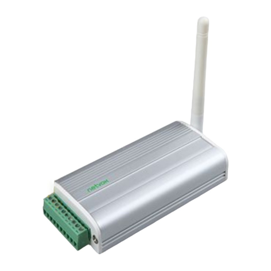
2. Product Appearance RS485-A RS485-B Permit-join USB power supply port Network key... -
Page 5: Specification
3. Specification Fully IEEE 802.15.4 compliant Utilizes 2.4GHz ISM band; up to 16 channels Power supply: 5V DC Up to 150 meters wireless transmission range in non-obstacle space Easy installation and configuration 4. Setting up ZL01B 4-1. - Page 6 2400bps, 1200bps. Default baud rate is 9600bps. If users would like to change baud rate, it must be done before leaving the factory or through Netvox OTA programming to modify. Process: Send GetPollData Request command via Z206/Z103A/B USB dongle. SendDataPayload is the real data needed to be sent to ZL01Bserial port.
-
Page 7: Restore To Factory Setting
RS485 of ZL01Bto the air and let another ZL01Breceives data and pass it through RS485 to the corresponding device. (3) Gateway mode: Sending data and receiving data are strictly following Netvox << Profile Standard Command.doc >> user manual. To switch the modes between mode 2 and gateway mode, please follow below command format:... - Page 8 8-bit integer 0xff 0x0003 HWVersion Unsigned 0x00 – Read only 0x0D 8-bit integer 0xff 0x0004 ManufacturerName Character 0 – 32 Read only netvox string bytes 0x0005 ModelIdentifier Character 0 – 32 Read only ZL01BE3C/ string bytes ZL01BE3R 0x0006 DateCode Character 0 –...
-
Page 9: Netvox App Interface
6. Netvox APP Interface 1. After the device is added to the Netvox system, the device information will appear on the device management interface of the APP. As shown in the figure below, the ZL01B device has one EP information. - Page 10 The identification button control part can make ZL01B enter the recognition state. If the screen is filled for 60s and then select the identification, ZL01B will enter the recognition state, flashing 60 times. Select the serial port parameter to read and modify the serial port related parameters. The following figure shows the current serial port configuration parameters of the device.
- Page 11 Select the serial port operation part of the control interface to enter the serial port template page of the device, as shown below.
- Page 12 You can download the serial port template by selecting the download button shown in the red box in the upper right corner. As shown below: ‘ Select the default heating device and enter the menred RS485 floor heating control interface. Through this interface, you can read the detection temperature of the menred LS6box;...
-
Page 13: Installation
7. Installation How to connect the product to the terminal device: 1. Interfacing with RS485 terminal equipment When connecting with the RS485 terminal device, only RS485-A is connected to the RS485-A interface of the docking device, RS485-B interface is connected to the RS485-B interface of the docking device, and GND is connected to the GND interface of the docking device. - Page 14 Device terminal interface ZL01 Interface RS232 interface ZL01 interface Figure 6-2. RS232 adapter cable...
- Page 15 RS232 Interface RS232 Interface USB Interface RS232 Interface Figure 6-4 Terminal device interface...
-
Page 16: Important Maintenance Instructions
8. Important Maintenance Instructions Please keep the device in a dry place. Precipitation, humidity, and all types of liquids or moisture can contain minerals that corrode electronic circuits. In cases of accidental liquid spills to a device, please leave the device dry properly before storing or using.
Need help?
Do you have a question about the ZigBee ZL01B and is the answer not in the manual?
Questions and answers