Table of Contents
Advertisement
Quick Links
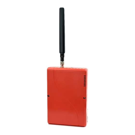
TG-7FP
Installation & Operation Guide
COMPANY CONFIDENTIAL
For use by TELGUARD customers only.
Distribution to other parties strictly prohibited.
November 20, 2020
Part Number 56052401
Rev. A
© 2020 Telguard. Telguard and the Telguard Logo are registered trademarks of
Telular Corporation | Telular is a business unit of AMETEK, Inc. All Rights Reserved.
Sole Path Communicator
Advertisement
Table of Contents
Troubleshooting

Subscribe to Our Youtube Channel
Related Manuals for Telguard TG-7FP


Summary of Contents for Telguard TG-7FP
- Page 1 Distribution to other parties strictly prohibited. November 20, 2020 Part Number 56052401 Rev. A © 2020 Telguard. Telguard and the Telguard Logo are registered trademarks of Telular Corporation | Telular is a business unit of AMETEK, Inc. All Rights Reserved.
- Page 2 Important Note The registration form must be completed before leaving for the job site to install the Telguard product. Use our dealer site at www.telguard.com to register the communicator in real time. Foreword Dealers purchase Telguard cellular communicators for the quality, features and total value they represent.
- Page 3 Cellular Alarm Communicator. Repair of this equipment should only be referred to qualified technical personnel. Telguard will repair or replace (our option) inoperative units for up to two years from date of manufacture. This excludes damage due to lightning or installer error.
- Page 4 INDEMNIFICATION OF TELGUARD YOU SHALL INDEMNIFY, DEFEND, AND HOLD HARMLESS TELGUARD FOR ANY OF THE COST, MISUSE OR IN A MANNER NOT CONTEMPLATED BY YOU AND TELGUARD OR INCONSISTENT WITH THE PROVISIONS OF THIS MANUAL; (ii) IN AN ILLEGAL MANNER OR AGAINST PUBLIC POLICY;...
-
Page 5: Table Of Contents
Pre-Installation Checklist Installation Summary Step 1: Register the Telguard Communicator Step 2: Physically Install the TG-7FP in Desired Location Step 3: Determine Antenna Placement for Best Performance Step 4: Connect to Panel DACT and Activate Step 5: Connect Supervisory Trip Outputs... - Page 6 Appendix 4 Commercial Fire 6-hour Supervision Appendix 5 Compliance with UL and ULC Standards Appendix 6 Detailed Specifications Dialer to Interface Electronics Power Digital Cellular Radio and Other Specifications Appendix 7 Accessories Telguard TG-7FP Installation & Operating Guide 56052401 Rev A...
-
Page 7: General Description And Operation
PSTN) or via the Internet (IP) to the desired alarm company central station for action. In a typical alarm installation, the TG-7FP is installed in the same area as the host alarm system and is connected directly to the host alarm panel via the TG-7FP -45 jack. -
Page 8: Information Related To Software Settings
24 hours (daily). BURGLARY SYSTEM INSTALLATIONS: In order to comply with the requirements in the Standard for Central-Station Burglar-Alarm Units, UL 1610 and Standard Line Supervision, the TG-7FP must meet these requirements: The TG-7FP communicator must be used in one of the following configurations: •... - Page 9 240s. • The TG-7FP shall be used in conjunction with a ULC or c-UL Listed Control Unit/Alarm Panel, which will supply power to operate the communicator. •...
-
Page 10: Features
No Service Condition (NSC) A no service condition (NSC) occurs when the TG-7FP is unable to register with the cellular network. NSC can be configured to trip the supervisory relay output (STC relay) after a programmable period of time. -
Page 11: Link Supervision
In Burglary installations, PPF must be set to Enabled. Link Supervision In order to satisfy UL and ULC requirements, the TG-7FP can enable link supervision at preset intervals. Once the TG-7FP is provisioned with the Link Supervision option, the TCC constantly monitors the cellular path and sends a specific message to the central station if the path is broken or a compromise attempt is made. -
Page 12: Telguard Automatic Self-Test Report
Although the communicator has the capability for an automatic self-test, a separate feature is provided for determining the current operational status of every Telguard communicator. This feature is called Check Status and is used to provide real-time operational status for the communicator on-demand. -
Page 13: Post-Installation Remote Programming
To change the device settings or accept updated firmware, follow these steps: • Locate and press either of the RSSI buttons on the TG-7FP, holding it for at least 5-7 seconds (use the provided tool or an unbent paper clip if using side button). •... -
Page 14: Ul And Ulc Compliance
Pre-Installation Checklist Before attempting to connect the communicator to the alarm panel, please make sure you have all the proper parts before you go to the job site. The following items are shipped with each TG-7FP: • Telguard Cellular Communicator •... -
Page 15: Installation
NOTE: Dealer Account Establishment and Telguard Registration must be complete prior to Installation. Step 1: Register the Telguard Communicator Installation Tip: Register for Telguard service prior to leaving for the job site to avoid a second trip. The registration form may be completed online through our 24/7 dealer portal www.telguard.com. -
Page 16: Step 2: Physically Install The Tg-7Fp In Desired Location
The message that is sent from the TCC to the central station is configurable in www.Telguard.com. The communicator will automatically be configured with a template that allows configuration of the trip input feature, including the message that is sent to the central station. -
Page 17: Step 3: Determine Antenna Placement For Best Performance
Connect the power and ground connections into the respective DC and GND connections on the TG-7FP using a supplied 2-position terminal block. NOTE: Do not use a plug-in adapter or other non-panel power source on the TG-7FP. The wiring used for power and other connections on the communicator can be either solid or... -
Page 18: Step 4: Connect To Panel Dact And Activate
The FACP and the Telguard communicator must both be located in the same room. Trip a zone on the alarm panel and confirm that the TG-7FP enables the alarm panel to transmit alarm events over the cellular radio network. The Telguard will confirm activation with the TCC if the registration form was completed prior to installation. -
Page 19: Step 5: Connect Supervisory Trip Outputs
If LED 1 and LED 4 are flashing, the communicator has failed activation. The serial number is not in the database at the TCC. Clear the fault (see note below) and call Telguard Technical Support to verify proper registration before resending an alarm signal. -
Page 20: Step 6: Connect And Test The Trip Input (Optional)
LED 3 starts to flash when the alarm panel goes off-hook to report the alarm signal over cellular. • No Service Condition (NSC): Disconnect the antenna from the TG-7FP. Check to see that the STC LED 2 flashes 4 times and if configured, alarm panel will detect the tripped STC after the selected period of time indicating loss of RF signal strength. -
Page 21: Appendix 1
Used when the communicator is working in a system that does not involve a Telco connection or a secondary path. In this case, the alarm panel is connected directly to the TG-7FP, and there is no other connection for communication. For commercial fire installations, a specific level of link supervision may be required (frequencies of 180 seconds, 5 minutes, or 60 minutes). - Page 22 Used when the communicator is working in a system that also involves a Telco connection or another communication path. In this case, both the TG-7FP and the alternate connections are being monitored by the Alarm Panel. It is the alarm panel that determines which communication path to use for signal delivery.
-
Page 23: Tamper Switch Installation For Ul/Ulc Commercial Burglary
For all UL/ULC Commercial Burglary Installations, a Tamper switch must be wired to monitor the TG-7FP enclosure. The wiring from Tamper Switch to the panel shall be in a rigid or flexible metal conduit along with other wiring from the TG-7FP to the Panel. -
Page 24: Rj-45 Jack Pin Assignments
Allows an external relay to 5 GND Trip Ground relay. trigger an alarm signal. LED 7 External trip Allows an external relay to 6 IN Trip Input relay. trigger an alarm signal. Telguard TG-7FP Installation & Operating Guide 56052401 Rev A... -
Page 25: Compatible Alarm Panels
TG-7FP: In order for the alarm panel to be compatible with the TG-7FP, the alarm panel must be programmed to transmit alarm messages to the central station using one of the following non-extended formats: Pulse Formats: 3+1 pulse;... -
Page 26: Appendix 2 Troubleshooting Guide
Appendix 2 Troubleshooting Guide This section provides a summary of all LED indications and their meanings, as well as the expected behavior of the TG-7FP under various exception conditions. LED Indicator Guide Normal Operating Mode LED Symbol Color Showing Indication... -
Page 27: Troubleshooting Quick Reference Table
TG-7FP can still receive when transmitting. (Initiated by TCC) (Status data) radio signals from the TCC. If several trouble conditions are present, the STC LED will flash all applicable indications in sequence. Telguard TG-7FP Installation & Operating Guide 56052401 Rev A... -
Page 28: Led Indicator Guide Rssi Mode
To use the side button, use the provided tool or an unbent paper clip. A simple press and release of either RSSI button will place the TG-7FP in RSSI mode and another simple press will exit RSSI mode. -
Page 29: Appendix 3 Commercial Fire Sole Path Installation
Appendix 3 Commercial Fire Sole Path Installation Starting with the 2010 edition of NFPA 72, the TG-7FP can be utilized as the sole path for fire communications. By following Telguard's installation guidelines, the installer can provide the best conditions for a stable, sole path connection. In order to ensure that the cellular path to be used for signaling has the highest reliability possible, it is necessary to confirm two additional conditions, beyond what is outlined above. -
Page 30: Appendix 4 Commercial Fire 6-Hour Supervision
6 hours, from an earlier version of 24 hours. This requirement is upheld in 2016 and 2019 edition as well. Telguard commercial fire products support this feature, and it must be enabled for each panel that uses more than one path, by selecting 6-hour supervision during registration. -
Page 31: Appendix 6 Detailed Specifications
Appendix 6 Detailed Specifications Dialer to Interface Electronics The integrated interface by Telguard allows digital dialers to dial into the cellular radio network. • Line voltage: -30 Vdc (default) or -40Vdc into standard telephone device when on-hook. • Dial tone: Precision 350 + 440Hz +/- 1%. 10 digits dial out capability. -
Page 32: Appendix 7 Accessories
50 feet of low loss high performance antenna cable and mounting bracket ACD-100 100 feet of low loss high performance antenna cable and mounting bracket HGDL-0 High Gain Directional Antenna EXDL-0 External Omni-Directional Antenna Telguard TG-7FP Installation & Operating Guide 56052401 Rev A...
Need help?
Do you have a question about the TG-7FP and is the answer not in the manual?
Questions and answers