Table of Contents
Advertisement
Quick Links
User Manual and Parts
Book
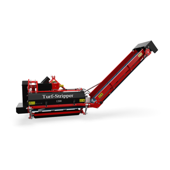
Turf-Stripper
Model 1200
Serial number:
Translation of original operating
instructions
ATTENTION:
IT IS OF THE UTMOST IMPORTANCE TO READ THIS USER MANUAL
CAREFULLY PRIOR TO USING THE TURF-STRIPPER IN ORDER TO USE THE
MACHINE SAFELY AND TO OBTAIN THE BEST RESULTS.
1702 English 953.120.000
Kwekerijweg 8
3709JA Zeist
The Netherlands
Tel.: (31)306933227
Fax: (31)306933228
Email:
verti-drain@redexim.com
www.redexim.com
Advertisement
Table of Contents

Related Manuals for Redexim Turf-Stripper 1200


Summary of Contents for Redexim Turf-Stripper 1200
- Page 1 Kwekerijweg 8 3709JA Zeist Model 1200 The Netherlands Tel.: (31)306933227 Fax: (31)306933228 Email: verti-drain@redexim.com Serial number: www.redexim.com Translation of original operating instructions ATTENTION: IT IS OF THE UTMOST IMPORTANCE TO READ THIS USER MANUAL CAREFULLY PRIOR TO USING THE TURF-STRIPPER IN ORDER TO USE THE MACHINE SAFELY AND TO OBTAIN THE BEST RESULTS.
-
Page 2: Warranty Conditions
FOREWORD Congratulations on your Turf-Stripper purchase! For safe and long-lasting operation of this Turf-Stripper, it is necessary to read and to understand this user manual. It is impossible to work safely with this machine without complete knowledge of the content of the user manual. -
Page 3: Safety Instructions
! SAFETY INSTRUCTIONS ! The Turf-Stripper is designed for safe use. This can only be achieved if you completely follow the safety instructions described in this manual. Read and understand (figure 1) the manual before you use the Easy Spread. If the machine is not used as described in this manual, this can result in injuries and/or damage Figure 1... - Page 4 Check the Turf-Stripper for loose bolts, nuts and components before every operation. If present, check the hydraulic pipelines regularly and replace these when the hydraulic pipelines are damaged or appear old. The pipelines that are replaced should comply with the technical requirements of the manufacturer. If a hydraulic installation is present, you should always make it pressure-free before working on this installation.
- Page 5 Check whether you have a clear field of vision – both close by and far away – before you depart. Safety stickers with an identical meaning are attached to the rear cover (Figure 5 and 6) and to both sides of the Turf-Stripper.
- Page 6 7. Location of the Turf-Stripper 1200 safety stickers (Figure 7). Used oil / grease is harmful to the environment. Dispose of these substances according to the regulations that apply in your location. Figure 7...
-
Page 7: Eu Declaration
EU DECLARATION We – Redexim BV, Utrechtseweg 127, 3702 AC Zeist, Holland – declare entirely under our own responsibility that the product: TURF-STRIPPER WITH A MACHINE NUMBER AS INDICATED ON THE MACHINE AND INDICATED IN THIS MANUAL to which this declaration refers, complies with stipulation of the 2006/42/EC machine... -
Page 8: Table Of Contents
TABLE OF CONTENTS WARRANTY CONDITIONS ..................2 REGISTRATION CARD ..................... 2 ! SAFETY INSTRUCTIONS ! ................. 3 EU DECLARATION ....................7 TECHNICAL DATA ..................9 GENERAL DESCRIPTION ................9 FIRST INSTALLATION – TAKING THE MACHINE OFF THE PALLET ..10 ATTACHING THE MACHINE TO THE TRACTOR ........11 THE POWER TAKE-OFF (PTO) ..............12 LENGTH OF THE PTO .......................... -
Page 9: Technical Data
1. TECHNICAL DATA 1.2m (47.2”) Working width Up to 50mm (2”) Working depth Up to 1,500mm (59.1”) Drain height Working speed The working speed depends on the conditions and the required result. It is maximum 3 km/h (1.8 mph). Weight in kg 620 kg (1367 lbs) Three-point connection Cat. -
Page 10: First Installation - Taking The Machine Off The Pallet
3. FIRST INSTALLATION – TAKING THE MACHINE OFF THE PALLET The machine is placed vertically on the pallet. To remove the pallet and to place the machine horizontally on the ground, take the following steps (see Figure 8) !! NEVER CRAWL UNDER THE MACHINE !! 1. -
Page 11: Attaching The Machine To The Tractor
4. ATTACHING THE MACHINE TO THE TRACTOR Checking procedure before starting to attach the Turf-Stripper. Check the Turf-Stripper for visually discernible damage and repair this if safe operation of the machine is no longer guaranteed. Check whether all the nuts and bolts are tight. ... -
Page 12: The Power Take-Off (Pto)
5. THE POWER TAKE-OFF (PTO) The PTO is a very important component. It also takes care of safe use of the machine, provided it is installed and maintained in the correct manner. The PTO has its own CE certification. Read the PTO manual. This manual is located on the PTO. Figure 10 LENGTH OF THE PTO The length of the PTO is very important. -
Page 13: Using The Pto
USING THE PTO The following items must be checked for correct use of the PTO: 1. While working the angle of the pivot pins may not exceed 30 degrees. 2. The pivot pins of the PTO on the tractor and on the machine must always be aligned. -
Page 14: Adjusting The Working Depth
7. ADJUSTING THE WORKING DEPTH Figure 11 The working depth is set by adjusting the front roller. The rear roller must be set to the long groove (A) for cutting and scarifying. Adjusting: 1. Adjust the rear spindles (2) to the correct position. For this purpose, use the indicator (see Figure 11) and block it by tightening the lock nut. -
Page 15: Transporting The Turf-Stripper
8. TRANSPORTING THE TURF-STRIPPER The user is responsible for transporting the Turf-Stripper in back of the tractor over public roads. Verify the national legislation regarding the regulations. On open fields while the machine is raised and if circumstances allow this, the maximum permitted speed is 12 km/h (8 mph) due to the weight of the Turf-Stripper. -
Page 16: Start/Stop Procedure
START/STOP PROCEDURE The start procedure is VERY important. If this procedure is not executed as described below, it might result in serious damage to the machine. The start procedure is as follows: 1. Check the Turf-Stripper for loose components and look whether all components function properly. -
Page 17: Detaching The Turf-Stripper
DETACHING THE TURF-STRIPPER Figure 12 The machine can be detached from the tractor in the following manner (See Figure 12) 1. Drive the Turf-Stripper to a parking area with a firm/flat surface. !! Make sure that the tractor is blocked well and cannot move on its own accord !! !! Switch off the tractor before descending !! !! Attention: the transport belt has to be tipped up !! -
Page 18: Trouble Shooting (Problem Analysis)
TROUBLE SHOOTING (PROBLEM ANALYSIS) Problem Possible cause Solution - Obstacle(s) between the - Remove the obstacle(s). Machine vibrates. knives - Worn or broken knives. - Replace with new knives. - Rotor is off-balance. - Balance the rotor. - Working depth is not adjusted - Adjust the working depth Working depth is not achieved. -
Page 19: Maintenance
MAINTENANCE Time schedule Check / Grease point Method - Check for loose bolts / nuts. - Tighten loose bolts / nuts with Before every use the correct tightening moment. - Check the oil level in the - Use SAE140. gearbox. - Presence and readability of the - Replace these if not present or safety stickers... -
Page 20: Lubricating Points
14.1 LUBRICATING POINTS Figure 13... -
Page 21: Adjusting The Tension Of The V-Belts
14.2 ADJUSTING THE TENSION OF THE V-BELTS Figure 14 The Turf-Stripper is standard equipped with adjustable tension pulleys that keep the V-belts taut. Depending on the intensity of using the machine, the driveline could be affected by wear and tear. These V-belts should then be tightened. -
Page 22: Conveyor Belt Alignment
14.3 CONVEYOR BELT ALIGNMENT Figure 15 If the conveyor belt starts slipping or moving sideways after a while or after new installation, please use the instruction as described below for re-tensioning: (See fig. 1) 1. At first check if the rollers and inside of the conveyor belt are clean. If necessary clean the polluted parts. -
Page 23: Optional: Scarifying Knives
OPTIONAL: SCARIFYING KNIVES The Turf-Stripper 1200 is standard equipped with cutting knives but it can also be equipped with scarifying knives (if required) for scarifying the subsoil. The distance between the knives can be set at 4 positions: 20mm (0.79”), 40 mm (2”), 60mm (2.36”) and 80mm (3.15”). - Page 24 Fig. 16 There are 8 rows on the rotor. Each row has 4 plates of which plate (1) is the extreme left one and plate (4) is the extreme right one, if you stand behind the machine (see Figure 15). These plates should be fitted with knives (K), distance bushes (B), counterweights (W), weather vanes (V) and small weather vanes (V2).
- Page 25 Distance between knives: Distance between knives: 20mm (0.79”) 40mm (1.57”) Plate Plate → → ↓ ↓ Knife 353.303.128 Knife 353.303.128 Counterweight 353.306.073 Counterweight 353.306.073 Distance bush 406.130.190 Distance bush 406.130.190 Bolt M10 x 30 804.100.300 Bolt M10 x 30 804.100.300 Bolt M10 x 35 804.100.350 Bolt M10 x 35...
- Page 26 Fig. 17...
Need help?
Do you have a question about the Turf-Stripper 1200 and is the answer not in the manual?
Questions and answers