Sign In
Upload
Download
Table of Contents
Contents
Add to my manuals
Delete from my manuals
Share
URL of this page:
HTML Link:
Bookmark this page
Add
Manual will be automatically added to "My Manuals"
Print this page
×
Bookmark added
×
Added to my manuals
Manuals
Brands
Hioki Manuals
Measuring Instruments
CM4003
Instruction manual
Hioki CM4003 Instruction Manual
Ac leakage clamp meter
Hide thumbs
Also See for CM4003
:
Instruction manual
(82 pages)
,
Instruction manual
(102 pages)
1
2
3
4
Table Of Contents
5
6
7
8
9
10
11
12
13
14
15
16
17
18
19
20
21
22
23
24
25
26
27
28
29
30
31
32
33
34
35
36
37
38
39
40
41
42
43
44
45
46
47
48
49
50
51
52
53
54
55
56
57
58
59
60
61
62
63
64
65
66
67
68
69
70
71
72
73
74
75
76
77
78
79
80
81
82
83
84
85
86
87
88
89
90
91
92
93
94
95
96
97
98
99
100
101
102
103
104
page
of
104
Go
/
104
Contents
Table of Contents
Troubleshooting
Bookmarks
Table of Contents
Checking Package Contents
Details of Intended Operations
Table of Contents
Introduction
Overview
Principle of Leakage Current Measurement
Notations
Options
Safety Information
Operating Precautions
Part Names
Operation Keys
Display Panel
Preparing for Measurement
Installing Batteries and the Z3210 Wireless Adapter
Installation/Replacement Procedure
Using an External Power Supply CM4003
Inspection Prior to Measurement
Performing Measurement
Measuring Leakage Current
Measurement Procedure
Locating an Insulation Failure (Identifying GFCI and RCD Trip Events)
Precautions for Measuring the Load Current
Filter Function (FILTER)
Hold Function (HOLD)
Max., Min., Average, and Peak Values (MAX/MIN)
Inrush Current Measurement (AC INRUSH)
Comparator Function (COMP)
Simple Event Recording Function
Output Function (OUTPUT) CM4003
Output Rate (A-To-V Conversion Ratio)
Setting the Output Function (RMS/WAVE)
Auto-Power Save Function (APS)
Backlight
Display Backlight
Warning Backlight
Wireless Communications Function
Using GENNECT Cross
Z3210-To-Excel ® Direct Data Entry Function (Excel ® Direct Input Function, HID Function)
Power Key Combinations
Specifications
General Specifications
Input, Output, and Measurement Specifications
Accuracy List
Output Specifications CM4003
Compatibility with IEC/EN 61557-13
Maintenance and Service
Calibration
Cleaning
Disposing of the Instrument
Troubleshooting
Before Sending the Instrument to be Repaired
Error Displays
Advertisement
Quick Links
Download this manual
CM4002
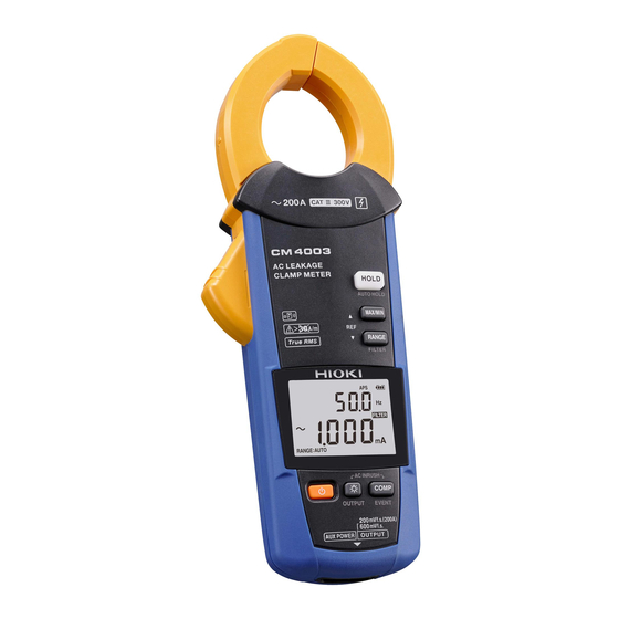
CM4003
AC LEAKAGE
CLAMP METER
Read carefully before use.
Keep for future reference.
Dec. 2021 Revised edition 2
CM4002A961-02 21-12H
HIOKI CM4002A961-02
Instruction Manual
EN
Table of
Contents
Previous
Page
Next
Page
1
2
3
4
5
Advertisement
Table of Contents
Need help?
Do you have a question about the CM4003 and is the answer not in the manual?
Ask a question
Questions and answers
Related Manuals for Hioki CM4003
Measuring Instruments Hioki CM4002 Instruction Manual
Ac leakage clamp meter (102 pages)
Measuring Instruments Hioki CM4002 Instruction Manual
Ac leakage clamp meter (82 pages)
Measuring Instruments Hioki CM4002-90 Instruction Manual
Ac leakage clamp meter (104 pages)
Hioki CM4001 - AC Leakage Clamp Meter Manual
(article)
Measuring Instruments Hioki CM4001 Instruction Manual
Ac leakage clamp meter (22 pages)
Measuring Instruments Hioki CM4001 Instruction Manual
Ac leakage clamp meter (28 pages)
Measuring Instruments Hioki CM4371 Instruction Manual
Ac/dc clamp meter (75 pages)
Measuring Instruments Hioki CM4375 Instruction Manual
Ac/dc clamp meter (72 pages)
Measuring Instruments Hioki CM4375 Instruction Manual
Ac/dc clamp meter (72 pages)
Measuring Instruments Hioki CM4141-50 Instruction Manual
Ac clamp meter (108 pages)
Measuring Instruments Hioki CM4141-90 Instruction Manual
Ac clamp meter (108 pages)
Measuring Instruments Hioki CM4373-50 Instruction Manual
Ac/dc clamp meter (124 pages)
Measuring Instruments Hioki CM4373-92 Instruction Manual
Ac/dc clamp meter (124 pages)
Measuring Instruments Hioki CM4375-91 Instruction Manual
Ac/dc clamp meter (124 pages)
Measuring Instruments Hioki CM4375-92 Instruction Manual
Ac/dc clamp meter (124 pages)
Measuring Instruments Hioki CM4373-91 Instruction Manual
Ac/dc clamp meter (124 pages)
This manual is also suitable for:
Cm4002
Cm4003-90
Cm4002-90
Table of Contents
Print
Rename the bookmark
Delete bookmark?
Delete from my manuals?
Login
Sign In
OR
Sign in with Facebook
Sign in with Google
Upload manual
Upload from disk
Upload from URL


Need help?
Do you have a question about the CM4003 and is the answer not in the manual?
Questions and answers