
Related Manuals for Hioki CM3286-50


Summary of Contents for Hioki CM3286-50
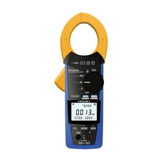
- Page 1 CM3286-50 Instruction Manual AC CLAMP POWER METER Read carefully before use. Keep for future reference. Dec. 2021 Edition 1 CM3286C961-00 21-12H HIOKI CM3286C961-00...
- Page 2 HIOKI CM3286C961-00...
-
Page 3: Table Of Contents
....................20 Installing and Replacing Batteries ............... 22 ■ Battery installation/replacement procedure ............. 23 Z3210 Wireless Adapter (option) ................25 ■ Z3210 Wireless Adapter installation/replacement procedure ......26 Test Leads ....................... 27 Inspection Before Measurement ................30 HIOKI CM3286C961-00 CM3286C961-00... - Page 4 Phase Detection [Phase Detect]................47 Single-phase Active Energy Measurement (Integrated Measurement) [Setting Wh] .............. 49 Single-phase Energy Meter Comparison Function [Setting Wh] ...... 51 ■ Setting the desired meter constant ..............55 Manual Hold, Automatic Hold ................57 HIOKI CM3286C961-00...
- Page 5 ■ General specifications ..................75 ■ Input, output, and measurement specifications ..........78 ■ Harmonic measurement specifications (with Z3210 connected) ..... 81 Accuracy Table ....................... 83 Equations ........................ 94 Maintenance and Service..................100 Troubleshooting ....................102 Warranty Certificate HIOKI CM3286C961-00...
- Page 6 Contents HIOKI CM3286C961-00...
-
Page 7: Introduction
Introduction Introduction Thank you for choosing the Hioki CM3286-50 AC Clamp Power Meter. To ensure your ability to get the most out of this instrument over the long term, please read this manual carefully and keep it available for future reference. - Page 8 • The Bluetooth word mark and logos are registered trademarks owned by Bluetooth SIG, Inc. and any use of such marks by Hioki E.E. Corporation is under license. Other trademarks and trade names are those of their respective owners. Precautions during shipment Handle it carefully so that it is not damaged due to a vibration or shock.
- Page 9 When you receive the instrument, inspect it carefully to ensure that no damage occurred during shipping. In particular, check the accessories, panel switches, and connectors. If damage is evident, or if it fails to operate according to the specifications, contact your authorized Hioki distributor or reseller.
- Page 10 The instrument screen displays the alphanumeric characters as follows. A B C D E F G H I J K L M N O P Q R S T U V W X Y Z 1 2 3 4 5 6 7 8 9 0 HIOKI CM3286C961-00...
-
Page 11: Options
Options Options The options listed below are available for the instrument. To order an option, please contact your authorized Hioki distributor or reseller. Options are subject to change. Please check Hioki's website for the latest information. Model C0207 Carrying Case... - Page 12 *10: CAT IV 1000 V, 2 A *11: CAT III 600V, 10 A *12: CAT II 600 V, 1000 A *13: When connecting the L4933 or L4934, configure the instrument for CAT II measurement. See “Test Leads” (p. 27). HIOKI CM3286C961-00...
-
Page 13: Safety Information
With regard to the electricity supply, there are risks of an electric shock, a heat generation, a fire, and an arc flash due to short‑circuit. Individuals using an electrical measuring instrument for the first time should be supervised by a technician who has experience in electrical measurement. HIOKI CM3286C961-00... - Page 14 Indicates prohibited actions. or serious injury to the operator. Indicates a potentially hazardous situation that may result in minor Indicates the action which CAUTION or moderate injury to the operator must be performed. or damage to the instrument or malfunction. HIOKI CM3286C961-00...
- Page 15 Symbols for various standards Indicates the Waste Electrical and Indicates that the product conforms to Electronic Equipment Directive (WEEE regulations set out by the EU Directive. Directive) in EU member states. HIOKI CM3286C961-00...
- Page 16 To prevent an electric shock, do not exceed the lower of the ratings shown on the instrument and connecting cords. Distribution panel Service entrance Internal wiring Service drop CAT II (≤1000 V) CAT III CAT IV (≤1000 V) (≤600 V) Outlet Power meter Fixed installation HIOKI CM3286C961-00...
-
Page 17: Precautions For Use
Attempting to do so could cause a short‑circuit Barrier or accident resulting in injury or death. Also, do not perform measurement around a bare conductor. • To prevent an electric shock, do not touch any areas beyond the barrier while the instrument is in use. HIOKI CM3286C961-00... - Page 18 It is recommended to make measurements on the secondary side of the distribution panel. Making measurements on the primary side of the panel, where currents are higher, poses a higher risk of instrument or equipment damage in the event of a short‑circuit. HIOKI CM3286C961-00...
- Page 19 CAT III or CAT IV measurement categories. (For measurement categories, see p. 10.) • If the sleeves are removed during measurement, stop the measurement. HIOKI CM3286C961-00...
- Page 20 • The cord is hardened in freezing temperature. Do not bend or pull it to avoid tearing its shield or cutting cord. IMPORTANT Inverter secondary-side waveforms and waveforms that include a large noise component may not be measured accurately. HIOKI CM3286C961-00...
- Page 21 Precautions for Use Current measurement precautions Do not clamp Do not touch. around two wires. Do not input Do not pinch wire excessively high between jaws. currents or voltages. (Flashes red) HIOKI CM3286C961-00...
-
Page 22: Part Names
Strap attachment hole MAX/MIN RANGE L9257 Connection Cord Alligator clip Connector Backlight key Voltage input terminal Cord (p. 10) (p. 11) * Do not touch any areas beyond the barrier while the instrument is in use. Sleeve Barrier* HIOKI CM3286C961-00... -
Page 23: Operation Keys
33 measurement during 3-phase the measurement display p. 44 power measurement (setting is not stored) Switches ranges p. 60 High speed count up (when – Count up (when setting meter setting meter constants) p. 55 RANGE constants) HIOKI CM3286C961-00... - Page 24 High speed count down Count down (when setting meter MAX/MIN p. 55 (when setting meter – constants) constants) Enables/disables the wireless Toggles the display backlight on and communications function p. 64 p. 66 (When connected to the Backlight Z3210, records settings.) HIOKI CM3286C961-00...
-
Page 25: Rotary Switch
• “Single-phase Energy Meter Comparison Function [Setting Wh]” (p. 51) • “AC single-phase measurement (1P2W) [var VA W]” (p. 38) • “AC single-phase measurement (1P3W) [var VA W]” (p. 39) “Current/Voltage Measurement (Frequency) [ ]” (p. 37) Turns off the instrument. HIOKI CM3286C961-00... -
Page 26: Power-On Option Table
W: Version of software the rotary switch.) Besides the above: Displays all indicators Switching between balanced p. 41 and unbalanced operation – – (during AC 3‑phase power p. 44 measurement) Beeping (on/off) – Saved HIOKI CM3286C961-00... - Page 27 Operation Keys Factory‑ Saving Setting Procedure shipped setting setting Switching the automatic p. 64 Saved backlight off function Selecting the CT ratio p. 65 Saved Reset to the factory shipped – – – setting HIOKI CM3286C961-00...
-
Page 28: Installing And Replacing Batteries
As the battery charge diminishes, black charge bars disappear, one (Appears) by one, from the left of the battery indicator. (Appears) The battery voltage is low. Replace the batteries as soon as possible. (Blinks) The battery is exhausted. Replace with new batteries. HIOKI CM3286C961-00... -
Page 29: Battery Installation/Replacement Procedure
If you have lost a screw or find that a screw is damaged, please contact your authorized Hioki distributor or reseller. Batteries may explode if mistreated. Do not short‑circuit, recharge, or disassemble the batteries, or dispose of them in fire. - Page 30 • Remove batteries from the instrument if it is to be stored for a long time. • Replace batteries only with the specified type. You will need: No. 2 Phillips screwdriver and LR03 Alkaline battery ×2 Recommended screw tightening torque: 0.7 Nm Exercise care to orient batteries properly. HIOKI CM3286C961-00...
-
Page 31: Z3210 Wireless Adapter (Option)
If you have lost any screws or find that any screws are damaged, please contact your authorized Hioki distributor or reseller. CAUTION Before handling the Z3210, eliminate static electricity from your body by touching any metallic part, such as a doorknob. -
Page 32: Z3210 Wireless Adapter Installation/Replacement Procedure
Remove the batteries. Remove the protective cap. Carefully checking the orientation, insert the 3210 all the way inside. Install the batteries. Rear Install the battery cover and tighten the screw. Recommended screw tightening torque: 0.7 N ・ m HIOKI CM3286C961-00... -
Page 33: Test Leads
The optional L9300 Test lead or L9207-10 Test Lead can be used for measurement. Depending on measurement locations, use our optional measurement cables. See “Options” (p. 5). L9300 Test Lead For measurement in category III, IV For measurement in category II L9207‑10 Test Lead Sleeve Sleeve HIOKI CM3286C961-00... - Page 34 The measurement category display changes when the protective finger guard is slid. For measurement in category III, IV Protective finger guard For measurement in category II Protective finger guard HIOKI CM3286C961-00...
- Page 35 Attaching the sleeve For measurement in category II Grip the base of the sleeves and pull the sleeves off. Store removed sleeves for future use. Removing the sleeve HIOKI CM3286C961-00...
-
Page 36: Inspection Before Measurement
Check the instrument for any damage that may have occurred during storage or shipping, and perform functional checks before use. If you find any damage to the instrument, please contact your authorized Hioki distributor or reseller for repair. Check item The battery cover is closed and its screw has been securely tightened. -
Page 37: Screen, Basic Operation
Displays the measured value. power measurement and phase detection. Connects the wire. Wire around which to clamp instrument Black Wires to which to clip connection cords IMPORTANT If measured with a wrong wire connection, a correct value does not appear. HIOKI CM3286C961-00... -
Page 38: Screen Display
CT ratio (not shown during 1/1) Measured value held *: The key lock feature may be activated according to the usage state of the Auto power save enabled application software. Current RMS value or voltage RMS value exceeded range Key lock enabled* HIOKI CM3286C961-00... -
Page 39: Switching The Information Shown On The Measurement Display
Sub2 display Sub3 display Current (frequency) Voltage (frequency) – – |PEAK| |PEAK| FREQ : Current frequency : Current RMS value : Current peak value |PEAK| FREQ : Voltage frequency : Voltage RMS value : Voltage peak value |PEAK| HIOKI CM3286C961-00... - Page 40 : Reactive power 3 PF : Power factor : Power factor 1 : Power factor 2 : Power factor 3 φ : Zero-cross phase angle 1 φ : Zero-cross phase φ : Zero-cross phase angle 2 angle 3 HIOKI CM3286C961-00...
- Page 41 *2: Different calculation methods are used for 3-phase/3-wire and 3-phase/4-wire circuits. For more information, see the list of equations. *3: Only 3-phase active power (P ), active power 1 (P ), and active power 2 (P ) are measured for 3-phase/3-wire circuits. HIOKI CM3286C961-00...
-
Page 42: Connecting The Clamp And Clips
If unable to connect the magnetic adapter so that it sits perpendicular to the terminal due to the weight of the voltage cord, connect it at an angle so as to balance it against the weight of the cord. HIOKI CM3286C961-00... -
Page 43: Current/Voltage Measurement (Frequency)
Clamp Measurement display* Voltage measurement “Switching the information shown on the measurement display” (p. 33) L/R/A If the screen turns red: Clip “Warning display” (p. 106) Black The frequency display Measurement flashes when frequency display* exceeds 999.9 Hz. HIOKI CM3286C961-00... -
Page 44: Power Measurement (Power, Power Factor)
Power Measurement (Power, Power Factor) AC single‑phase measurement (1P2W) [var VA W] Select the Clamp desired function. and clip L/R/A Black “Switching the information Measurement display* shown on the measurement display” (p. 33) If the screen turns red: “Warning display” (p. 106) HIOKI CM3286C961-00... -
Page 45: [Var Va W]
AC single‑phase measurement (1P3W) [var VA W] Clamp Select the desired function. and clip Black Black Clamp and clip Measurement display* “Switching the information shown on the measurement display” (p. 33) If the screen turns red: “Warning display” (p. 106) HIOKI CM3286C961-00... -
Page 46: [3Pw]
(p. 33) If the screen turns red: “Warning display” (p. 106) When the balanced 3-phase 3-wire zero-cross phase angle is less than −90° or exceeds 90°, the measured value appears “ – – – – ” . HIOKI CM3286C961-00... -
Page 47: [3Pw]
• Proceed to the next step Measurement display 1 after verifying that the (active power 1) Connection display 2 measured values shown on measurement displays 1 and 2 are normal. • If the screen turns red: “Warning display” (p. 106) HIOKI CM3286C961-00... - Page 48 “ − ” appears beside it. Displays alternately 3-phase active power Active power 1 Active power 2 Hold down the key for 1 s or longer. The measured value is cleared and returns to the initial connection display. HIOKI CM3286C961-00...
-
Page 49: [3Pw]
L3/T/C Black Hold down the key for 1 s or longer Measurement display (calculation result)* Connection display (p. 31) If the screen turns red: “Warning display” (p. 106) “Switching the information shown on the measurement display” (p. 33) HIOKI CM3286C961-00... -
Page 50: [3Pw]
Hold down the key for 1 s or Black longer. Connection display 1 (p. 31) To next page Measurement display 1 Connection display 2 (active power 1) Proceed to the next step after verifying that the measured values shown on measurement display 1 is normal. HIOKI CM3286C961-00... - Page 51 L1/R/A and clip L2/S/B L3/T/C Black Connection display 3 Measurement display 3 (active power 3) To next page Proceed to the next step after verifying that the measured values shown on measurement displays 2 and 3 are normal. HIOKI CM3286C961-00...
- Page 52 The measured value is cleared and returns to the initial connection display. • You can switch the information shown on the final measurement display with the key. See “Switching the information shown on the measurement display” (p. 33) • If the screen turns red: “Warning display” (p. 106) HIOKI CM3286C961-00...
-
Page 53: Phase Detection [Phase Detect]
• When the input is unstable, the second connection display will not show up. Line voltage (1 measurement) *: If not clipped within 10 s, Countdown display it is unable to make a measurement. HIOKI CM3286C961-00... - Page 54 Phase Detection [Phase Detect] Measurement display Reverse phase Normal phase Display appears in the order of the arrow. Display of results Line voltage (2 measurement) (Lights red) Goes back to the first display when the HOLD key is pressed. HIOKI CM3286C961-00...
-
Page 55: Single-Phase Active Energy Measurement
Single-phase Active Energy Measurement (Integrated Measurement) [Setting Wh] Single‑phase Active Energy Measurement (Integrated Measurement) [Setting Wh] Select the Clamp and clip desired function. L/R/A Set the constant number Black to OFF. To next page HIOKI CM3286C961-00... - Page 56 • The measured values are automatically stored just before the instrument turns off due to low battery voltage. Next time the instrument is turned on, the saved values will be displayed. (The measured values can be cleared by pressing the HOLD key.) HIOKI CM3286C961-00...
-
Page 57: Single-Phase Energy Meter Comparison Function [Setting Wh]
• If the instrument is being used in close proximity to a device that emits a strong magnetic field, for example a transformer, high-current circuit, or wireless device. HIOKI CM3286C961-00... - Page 58 Once the disc has completed one revolution When the LED flashes once Start integration Start integration Disc Stop integration Stop integration Fixed energy mode e.g.: With the fixed energy set to 0.1 kWh Start integration 0.1 kWh digit Stop integration HIOKI CM3286C961-00...
- Page 59 To next page *: Select fixed energy mode if the energy meter’s disc rotates, or if its LED flashes, quickly. The constant can be changed. “Energy meter comparison function settings screen” (p. 56) “Setting the desired meter constant” (p. 55) HIOKI CM3286C961-00...
- Page 60 Energy ratio (Measured value / theoretical value) Energy difference (Measured value − theoretical value) Energy (Measured value) HOLD When the key is pressed during integration stop, the integrated energy clears and returns to the display shown in Step 4. HIOKI CM3286C961-00...
-
Page 61: Setting The Desired Meter Constant
The set value will be stored. • Press the key to go back to the measurement display. • The changed final value will be the setting value. • “Energy meter comparison function settings screen” (p. 56) HIOKI CM3286C961-00... - Page 62 125 cyc./1 kWh no. 04 0.10 kWh 1000 cyc./1 kWh 0.10 kWh – no. 05 600 cyc./1 kWh 0.05 kWh 0.05 kWh – no. 06 0.01 kWh 500 cyc./1 kWh 0.01 kWh – HIOKI CM3286C961-00...
-
Page 63: Manual Hold, Automatic Hold
Pressing the HOLD key again appears) cancels the measured value hold function. Holding down the HOLD key for 1 s to disable the disappear) automatic hold function. ( disappear). See the next page for automatic hold conditions. HIOKI CM3286C961-00... - Page 64 If the measured value* (voltage, current, or power) falls below the threshold value once and the two conditions are satisfied again after automatic retaining, the measured value at that point will retain automatically. *: Either the current RMS value or voltage RMS value for power. HIOKI CM3286C961-00...
- Page 65 Current and voltage RMS values satisfy Current and voltage RMS values are balanced 3-phase above conditions, and active power is within the above counts. power within 5 counts. *: No automatic hold function is available for single-phase active energy measurement. HIOKI CM3286C961-00...
-
Page 66: Switching Ranges
Switching Ranges Switching Ranges e.g.: During current measurement Automatic range MANUAL 600.0 A range MANUAL 60.00 A range MANUAL 6.000 A range HIOKI CM3286C961-00... -
Page 67: Max., Min., And Average Values (Max/Min/Avg)
• The maximum and minimum values are automatically stored just before the instrument turns off due to low battery voltage. Next time the instrument is turned on, the saved values will be displayed. (The measured values can be cleared by pressing the HOLD key.) HIOKI CM3286C961-00... - Page 68 Also, only the maximum and minimum values are shown during zero-cross phase angle measurement.) *2: Measured value's update time is displayed when maximum or minimum value is shown. Elapsed time from the start of maximum, minimum, and average function is displayed when present or average value is shown. HIOKI CM3286C961-00...
- Page 69 MAX: Maximum value after pressing the MAX/MIN MIN: Minimum value after pressing the MAX/MIN |PEAK|: Maximum value of the absolute value of the waveform during the display update interval |PEAK| MAX: Minimum value of |PEAK| after pressing the MAX/MIN HIOKI CM3286C961-00...
-
Page 70: Backlight, Automatic Power Save (Aps)
• The APS function is disabled while displaying the MAX/ MIN/AVG value and during energy integration. Switching the auto backlight off • Wireless communications are considered to be in operation function: p. 21 and do not correspond to no operation. HIOKI CM3286C961-00... -
Page 71: Measurement Using The Clamp Adapter
Select the CT ratio. 1/1 (not shown) 1/10 1/100 1/1000 Set the CT ratio as appropriate for the clamp adapter. (e.g.: For the 9290-10 Clamp on Adapter, 1/10) Perform measurement. Clamp Conductor Clamp Clamp adapter (e.g.: Model 9290-10) The instrument HIOKI CM3286C961-00... -
Page 72: Wireless Communications Function
Enabling the wireless communications function allows you to check the measured data of the instrument, and create measurement reports using your mobile device. For details, see the operation guide for the GENNECT Cross app (free of charge). GENNECT Cross special site https://gennect.net/en/cross/index HIOKI CM3286C961-00... - Page 73 Cross and the instrument. • When you turn on the instrument for the first time after installing the Z3210, the instrument will start with the wireless communications function enabled. The setting will be retained even after power off. HIOKI CM3286C961-00...
- Page 74 The display will show the icon. Hold down for 1 s. Start GENNECT Cross and register the instrument to connect. Select each function and perform measurement. For detail information, please visit our website. GENNECT Cross > Functions https://gennect.net/en/cross/function HIOKI CM3286C961-00...
- Page 75 Wireless Communications Function Turning on and off the wireless communications function Wireless communications function OFF Wireless communications function ON Hold down the key for 1 s or longer. icon will flash when the instrument is connected to a mobile device. HIOKI CM3286C961-00...
- Page 76 Up to 99 events can be recorded. If events has reached 99, the event recording will stops. When another event recording starts, previously recorded data will be deleted. Some events with a duration time of less than 1 s may not be accurately measured, failing to detect them. HIOKI CM3286C961-00...
-
Page 77: Z3210-To-Excel ® Direct Data Entry Function (Excel ® Direct Input Function, Hid Function)
(p. 57) HID OFF When you wish to use GENNECT Cross, disable the HID function. The setting whether the HID function has been enabled or disabled will not be saved in the instrument but in the Z3210. HIOKI CM3286C961-00... - Page 78 The HID setting saved in the Z3210 will be displayed. Confirm the HID setting. When the HID function is enabled Regular display Release reappears. key. When the HID function is disabled When “−−−−” is displayed Update the Z3210 to the latest version using GENNECT Cross. HIOKI CM3286C961-00...
- Page 79 OFF position. Chang the HID setting. After the setting is toggled between on and off, the instrument is automatically turned off. The instrument is automatically turned off. Turn on the instrument again. The HID setting will be toggled. HIOKI CM3286C961-00...
- Page 80 2. Disable the Z3210’s HID function. (p. 73) 3. Use the Instrument Setting of GENNECT Cross to reconnect the instrument. For detail information, please visit the Z3210’s website. https://z3210.gennect.net HIOKI CM3286C961-00...
-
Page 81: Specifications
−25°C (−13°F) or higher but less than 40°C (104°F): 80% RH or less 40°C (104°F) or higher but less than 45°C (113°F): 60% RH or less 45°C (113°F) to 65°C (149°F): 50% RH or less (non-condensing) Remove batteries before storing the instrument. HIOKI CM3286C961-00... - Page 82 0: The equipment inside the enclosure is not protected against the harmful effects of water. Standards Safety: EN 61010 EMC: EN 61326 Power supply LR03 alkaline battery ×2 Rated supply voltage: 1.5 V DC × 2 Maximum rated power: 1200 mVA HIOKI CM3286C961-00...
- Page 83 Jaw dimensions Approx. 79Wj × 20Dj mm (3.11″W × 0.79″D) Maximum measurable φ46 mm conductor diameter Weight Approx. 450 g (15.9 oz.) (including batteries) Product warranty 3 years duration Accessories See p. 3 Options See p. 5 HIOKI CM3286C961-00...
-
Page 84: Input, Output, And Measurement Specifications
600 V AC (Measurement category IV), 1000 V AC (Measurement category III) to earth Anticipated transient overvoltage 8000 V Maximum measuring 600 V AC voltage Measurement method True RMS measurement with digital sampling Measurement terminals COM terminal, V terminal Ω Input impedance or greater HIOKI CM3286C961-00... - Page 85 (voltage) frequency, power factor, and zero-cross phase values are shown as “– – – –.” • A value of 0 is used in single-phase active energy calculations. Frequency derating characteristics 1000 10000 周波数 [Hz] Frequency [Hz] HIOKI CM3286C961-00...
- Page 86 Accuracy guarantee Accuracy guarantee duration: 1 year conditions Accuracy guarantee duration after adjustment made by Hioki: 1 year Accuracy guarantee temperature and humidity range: 23°C ±5°C (73°F ±9°F), 80% RH or less (non-condensing) Number of jaw open/close cycles: 10000 times or less...
-
Page 87: Harmonic Measurement Specifications (With Z3210 Connected)
(RMS values for current harmonics [A], RMS values for voltage harmonics [V]) Harmonic content percentage (content percentages for current harmonics [%], content percentages for voltage harmonics [%]) Total harmonic distortion (THD-F and THD-R for current [%], THD-F and THD-R for voltage [%]) HIOKI CM3286C961-00... - Page 88 ±5.0% rdg ±10 dgt 11 to 20 ±10% rdg ±10 dgt 21 to 30 ±20% rdg ±10 dgt Harmonic content ±1 dgt for calculations performed using measured values percentage Total harmonic ±1 dgt for calculations performed using measured values distortion HIOKI CM3286C961-00...
-
Page 89: Accuracy Table
60.00 A ±3.0% rdg (0.60 A to 60.00 A) ±5 dgt 0.00 A to 60.00 A ±1.0% rdg ±1.5% rdg ±3 dgt ±5 dgt 0.1 A 600.0 A – (6.0 A to 600.0 A) 0.0 A to 600.0 A HIOKI CM3286C961-00... - Page 90 150 count. Current frequency range) values of less than 45.0 Hz are shown Display range as “– – – –.” 0.1 Hz 999.9 Hz ±0.3% rdg ±3 dgt (45.0 Hz to 999.9 Hz) 45.0 Hz to 999.9 Hz HIOKI CM3286C961-00...
- Page 91 (Accuracy guarantee Maximum less than 150 count. Voltage frequency range) display values of less than 45.0 Hz are shown as “– – – –.” 0.1 Hz 999.9 Hz ±0.3% rdg ±3 dgt (45.0 Hz to 999.9 Hz) 999.9 Hz HIOKI CM3286C961-00...
- Page 92 108.0 kW 1080 kW (P / P (3P4W) 4‑Wire (0.01 kW) (0.1 kW) (1 kW) Accuracy (Power factor =1) Single‑ ±2.0% rdg ±1.7% rdg ±5 dgt phase ±7 dgt 3‑Phase ±2.0% rdg ±1.7% rdg ±2 dgt 4‑Wire ±3 dgt HIOKI CM3286C961-00...
- Page 93 0.0° to 179.9° *: Value is calculated based on the measurement of the zero-cross phase difference for the voltage and current waveforms (positive [no sign] when the current lags the voltage and negative when the current leads the voltage). HIOKI CM3286C961-00...
- Page 94 The unit [W] is replaced by [VA] for apparent power values. apparent power (3P3W) Balanced Accuracy ±1 dgt relative to calculation from measured values 3‑phase/3‑wire Range For the above active power range configuration, the unit [W] is replaced reactive power configuration by [var]. (3P3W) HIOKI CM3286C961-00...
- Page 95 Single‑phase active energy measurement (AC) Effective Current RMS value (I 0.060 A to 600.0 A Value must fall within the current measuring measurement range’s guaranteed accuracy range range. Voltage RMS value (U 80.0 V to 600.0 V Frequency 50 Hz/60 Hz HIOKI CM3286C961-00...
- Page 96 The time is incremented by 1 s from 00:00 time display [min:sec]. When 59:59 [min:sec] is exceeded, the range is switched to the 48:00 [hour:min] 48:00 [hour:min] range. During integration using the 48:00 [hour:min] range, the “ : ” display flashes every 0.5 s. HIOKI CM3286C961-00...
- Page 97 Reverse phase (Display: 321) Open phase or unable to measure (Display: “ – – – –”) *: Measurement is not possible if the second measured value fails to stabilize within 10 s once the display changes to the second measurement screen. HIOKI CM3286C961-00...
- Page 98 360.0 kW. Single-phase CT ratio 1/1 Same accuracy 36.00 kW 360.0 kW 3600 kW – active power specifications as 36.00 kW. CT ratio 1/1 Same accuracy 3.600 kW 36.00 kW 360.0 kW 3600 kW specifications as 3.600 kW. HIOKI CM3286C961-00...
- Page 99 • The unit is replaced as below for apparent power and reactive power, relative to the active power range. Apparent power: kVA Reactive power: kVAR *1: Multiply the digit error indicated in the accuracy specifications noted in the “Remarks” column by 10. HIOKI CM3286C961-00...
-
Page 100: Equations
⋅ ⋅ (3P3W) • The symbol S represents active power the apparent power of the Balanced 3‑phase/3‑wire line voltage U and the wire S ⋅ (3P3W) apparent power [VA] current I Balanced 3‑phase/3‑wire − (3P3W) reactive power [var] HIOKI CM3286C961-00... - Page 101 • The symbol P2 represents the active power of Unbalanced 3‑phase/3‑ (UB3P3W) P1+P2 the line voltage U and the wire current 1 wire active power • The active power P has no sign during consumption and a negative sign during generation. HIOKI CM3286C961-00...
- Page 102 (UB3P4W) S1+S2+S3 current I apparent power [VA] • The symbol S3 represents the apparent power of the phase voltage U and the wire current I • Due to the effects of measurement error, S=|P| is used when S<|P|. HIOKI CM3286C961-00...
- Page 103 [var] • The symbol Q3 represents the reactive power of the phase voltage U and the wire current I • Due to the effects of measurement error, Q=0 is used when S<|P|. Unbalanced 3‑phase/4‑wire – (UB3P4W) power factor HIOKI CM3286C961-00...
- Page 104 Equations (Reference) Harmonic calculations Calculated by GENNECT Cross RMS value – Harmonic content × percentage for k th order – ∑ Harmonic current THD-F × Total harmonic distortion ∑ × THD-R ∑ HIOKI CM3286C961-00...
- Page 105 – ∑ Harmonic voltage THD-F × Total harmonic distortion ∑ × THD-R ∑ Index k: Analyzed order r: Post-FFT resistance component i: Post-FFT reactance component I′: Current sampling value U′: Voltage sampling value HIOKI CM3286C961-00...
-
Page 106: Maintenance And Service
• Wipe the LCD gently with a soft, dry cloth. IMPORTANT Never use solvents such as benzene, alcohol, acetone, ether, ketone, thinners or gasoline. Doing so could deform and discolor the instrument. Disposal Handle and dispose of the instrument and batteries in accordance with local regulations. HIOKI CM3286C961-00... - Page 107 The calibration period varies with the conditions and environment of use. It is recommended to determine a calibration period based on those factors and to have the instrument regularly calibrated by Hioki. Please contact your Hioki distributor to have your instrument periodically calibrated.
-
Page 108: Troubleshooting
Troubleshooting Troubleshooting If damage is suspected, check the following before contacting your authorized Hioki distributor or reseller. Problem Cause Remedy The instrument The measured value is lower Wrap the wire around the jaw one or is indicating an than the lower limit value of more times. - Page 109 (vibration). measured. measurement. The measured value The connection cords have Check the continuity of the connection does not appear. a break. cords. If a break is found, replace the connection cords. HIOKI CM3286C961-00...
- Page 110 The connection cords are Insert the connection cords all the way. is displayed even not inserted all the way. when the connection cords are shorted. If problems cannot be resolved even after you have implemented such remedies, have the instrument repaired. HIOKI CM3286C961-00...
- Page 111 Err 008 Z3210 communication error or is not properly that one. connected If the error continues to be displayed, the instrument needs to be repaired. Please contact your authorized Hioki distributor or reseller. HIOKI CM3286C961-00...
- Page 112 Display Buzzer Cause Solution The instrument may not Measurement be connected properly. Flashes – resulted in a negative Reconnect the instrument active power value. to the circuit being measured. Phase detection Lights Intermittent indicated reverse – sound phase. HIOKI CM3286C961-00...
- Page 113 6 A and 60 A range, this warning display will not appear. A current or voltage Change the measurement Lights exceeding the range – range or select the AUTO was input while using range. a manual range. e.g.: for current measurement HIOKI CM3286C961-00...
- Page 114 Troubleshooting HIOKI CM3286C961-00...
- Page 115 HIOKI CM3286C961-00...
- Page 116 HIOKI CM3286C961-00...
- Page 117 HIOKI CM3286C961-00...
- Page 118 HIOKI CM3286C961-00...
Need help?
Do you have a question about the CM3286-50 and is the answer not in the manual?
Questions and answers