
Related Manuals for Hioki CT6710


Summary of Contents for Hioki CT6710
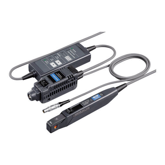
- Page 1 CT6710 CT6711 Instruction Manual CURRENT PROBE Feb. 2019 Edition 1 CT6710A961-00 19-02H...
- Page 3 Measurement Procedure Be sure to familiarize yourself with the “Usage Notes” section (p. 8 ), each instruction of use, and safety notes presented at the beginning of each instruction of use. Inspecting the Device Before Use (p. 2 6) Preparing for Measurement (p. ...
- Page 4 Connection Example Waveform measuring instrument Power source Load Model 3269 Power Supply See “Example of connection to the circuit to be measured” (p. 4 8).
-
Page 5: Table Of Contents
Contents Introduction ................1 Notations ................2 Confirming Package Contents ..........5 Safety Notes .................7 Usage Notes .................8 Overview Product Overview ..........13 Product Features ..........14 Name and Function of Each Part ....16 Termination unit ............16 Junction box (keys, LEDs) ........18 Sensor ..............20 Specifications of Lighting up / Blinking LEDs ...............22 Current Measurement... - Page 6 Contents Specifications General Specifications ........67 Specifications of Input, Output, and Measurement ..........69 Basic specifications ..........69 Specifications of accuracy ........71 Specifications of Functionality ......73 Typical Characteristics ........75 Frequency characteristics ......... 75 Frequency derating curve ......... 76 Input impedance ............78 Consumption current ..........
-
Page 7: Introduction
Introduction Introduction Thank you for choosing the Hioki CT6710, CT6711 Current Probe. Preserve this manual carefully and keep it handy to make full use of this device for a long time. Each model offers a different frequency band listed below:... -
Page 8: Notations
Notations Notations Safety notations In this manual, the risk seriousness and the hazard levels are classified as follows. Indicates an imminently hazardous situation DANGER that will result in death or serious injury to the operator. Indicates a potentially hazardous situation WARNING that may result in death or serious injury to the operator. - Page 9 Notations Indicates prohibited actions. Indicates an action that must be performed. Symbols shown on the device Indicates cautions and hazards. When this symbol is displayed on the device, refer to the “Usage Notes” section (p. 8 ) and warning messages presented at the beginning of each instruction of use in the Instruction Manual, and included “Current Sensor Operating Precautions”...
- Page 10 Notations Others Additional information is presented below. Bold Keys of the device are indicated in boldface. Accuracy We define measurement tolerances in terms of rdg. (reading) with the following meanings: (reading or displayed value) rdg. The value currently being measured and indicated on a measuring instrument.
-
Page 11: Confirming Package Contents
Check the accessories, keys, and connectors carefully. If the device seems to have been damaged or does not work as specified, contact your authorized Hioki distributor or reseller. Check that the package contents are correct. Model CT6710/CT6711 Current Probe Accessories ... - Page 12 Confirming Package Contents Option The following option is available for the device. Contact your authorized Hioki distributor or reseller when ordering. Model 3269 Power Supply Model 3269 can provide the power to up to two probes of Model CT6710 or Model CT6711.
-
Page 13: Safety Notes
Safety Notes Safety Notes This device is designed to conform to IEC 61010 Safety Standards and has been thoroughly tested for safety prior to shipment. However, using the device in a way not described in this manual may negate the provided safety features. Carefully read the following safety notes before using this device. -
Page 14: Usage Notes
Usage Notes Usage Notes Follow these precautions to ensure safe operation and to obtain the full benefits of the various functions. Ensure that your use of the device falls within the specifications not only of the device itself, but also of any accessories, options and other equipment being used. - Page 15 Usage Notes DANGER • Do not remove any covers of the sensor, junction box, and termination unit. The internal components of the device carry high voltages and may become very hot during operation. Making contact with them could cause an electric shock and burns. •...
- Page 16 Usage Notes WARNING • Do not use the device to measure circuits that exceed the ratings or specifications of the device. Damage to the device or overheating can cause bodily injury. • Do not install the device in the following locations.
- Page 17 Any damage to the device leads to an electric shock. Contact your authorized Hioki distributor or reseller for repair. CAUTION • Do not place the device on an unstable surface or an inclined place.
- Page 18 Usage Notes CAUTION • Keep the upper jaw locked in place when the device is not in use. Leaving the upper jaw unlocked causes dust or dirt to settle on the facing core surfaces, which can damage the device. • Properly connect the device to a circuit to be measured and a host waveform measuring instrument.
-
Page 19: Overview
Overview 1.1 Product Overview Model CT6710/CT6711 is a clamp-on current probe that features high current-detection sensitivity and broad frequency band. The probe uses three current ranges to detect current waveforms from 1 mA to 50 A. You can directly connect the termination unit to a BNC input... -
Page 20: Product Features
Product Features 1.2 Product Features Clamp-on sensor heads (p. 2 1) The clamp-on sensor heads allow current measurement without the need to make physical contact with a conductor to be measured, or to disconnect it. You can observe current waveforms while maintaining the flow of electric current. - Page 21 This feature lets you observe a wide range of currents, from 1 mA to 50 A. Broad frequency band (p. 6 9) Model CT6710: DC to 50 MHz Model CT6711: DC to 120 MHz Demagnetizing and automatic zero-adjustment functions (p. ...
-
Page 22: Name And Function Of Each Part
Name and Function of Each Part 1.3 Name and Function of Each Part Termination unit See p. 3 3 and p. 3 4. Top view... - Page 23 Required for production control. Do not peel off the label. Power plug Power is provided to Model CT6710/CT9711 through this plug. Connect this plug with Model 3269 Power Supply. Shell Pull on the power plug while simultaneously pulling this shell to disconnect the plug.
-
Page 24: Junction Box (Keys, Leds)
Name and Function of Each Part Junction box (keys, LEDs) Top view DEMAG / AUTO ZERO Hold down Performs demagnetization followed by (about 1 s) automatic zero-adjustment (p. 3 3). Press momentarily Performs automatic zero-adjustment (less than 0.5 s) alone (p. 3 9). (Higher range) key (p. ... - Page 25 Name and Function of Each Part POWER LED (green light) • Lights up when the power is on (p. 3 1). • Blinks rapidly when a checksum error has occurred (p. 9 3). OVERLOAD LED (red light) • Blinks three times when demagnetizing or automatic zero- adjustment cannot be performed (p. ...
-
Page 26: Sensor
Name and Function of Each Part Sensor CAUTION Avoid doing the following acts. Doing so could damage to the sensor heads. • Storing and using the device in locations subject to abrupt temperature changes • Applying force or mechanical shock to the device •... - Page 27 Name and Function of Each Part Jaws Clamp this part around a conductor to be measured by operating the opening lever, which allows the upper jaw to slide (retract/extend). Sensor aperture A conductor to be measured must pass through this aperture.
-
Page 28: Specifications Of Lighting Up / Blinking Leds
Specifications of Lighting up / Blinking LEDs 1.4 Specifications of Lighting up / Blinking LEDs : Lighting up : Off : Blinking Device state Green Automatic zero- Overload Others POWER adjustment − − (On start-up) 2 Not performed Not detected (Initial state) In execution −... - Page 29 Specifications of Lighting up / Blinking LEDs : Lighting up : Off : Blinking Orange Green DEMAG / AUTO RANGE OVERLOAD JAW UNLOCKED ZERO 30 A 0.5 A Slowly* ...
- Page 30 Specifications of Lighting up / Blinking LEDs...
-
Page 31: Current Measurement
Current Measurement WARNING • Do not clog the vents on the sides and bottom of the termination unit (p. 1 6). Doing so can cause a breakdown or fire due to internal overheating. • Do not cover the junction box (p. 1 8) with a cloth or pile the box on another. -
Page 32: Inspecting The Device Before Use
• Model 3269 Power Supply (available as an option) • Waveform measuring instrument (such as oscilloscope and recorder) Connecting the device to a Hioki Memory HiCorder with a power supply module for current probes (option) installed allows the device to operate without Model 3269 Power Supply. - Page 33 Inspecting the Device Before Use Inspecting appearance and functionality of the device and condition of conductors to be measured Are the sensor, junction Send the device for box, and termination unit repair. Damage can damaged? cause an electric shock. Send the device for Is the insulation of each repair.
-
Page 34: Preparing For Measurement
Preparing for Measurement 2.2 Preparing for Measurement WARNING Turn off all the instrument before connecting the device. Failure to observe this can cause an electric shock and short-circuit. CAUTION • Confirm that the supply voltage to Model 3269 Power Supply (option) matches the supply voltage indicated on the rear panel of the 3269 before connecting the power cord to the 3269. -
Page 35: Providing Power To The Device
For information about the consumption current, see “Consumption current” (p. 7 9) in “Typical Characteristics”. Model 3272 Power Supply, which does not have sufficient current capacity, cannot activate Model CT6710/CT6711. - Page 36 Preparing for Measurement How to provide the power to the device Confirm that the POWER switch of Model 3269 Power Supply is OFF. Connect the power cord to the power inlet on the back of the 3269. Slide the opening lever of the sensor toward the lower jaw until the UNLOCKED...
- Page 37 The LEDs of the probes and power supply light up or blinks as follows: Model 3269 POWER indicator lights up. Model CT6710/CT6711 After all LEDs light up for 1 second, the device operates as follows: • The POWER LED lights up.
- Page 38 Preparing for Measurement Wait for 30 minutes or more. Wait at least 30 minutes after starting to supply power to the device to accurately measure a current before executing demagnetization and automatic zero-adjustment. See “Executing demagnetization and automatic zero- adjustment” (p. 3 3). Do not execute demagnetization and automatic zero-adjustment or measure a current immediately after starting to supply the power to...
-
Page 39: Executing Demagnetization And Automatic Zero- Adjustment
Preparing for Measurement Executing demagnetization and automatic zero- adjustment CAUTION • Do not rotate the output terminal while the termination unit is connected with a waveform measuring instrument. Moreover, do not apply force to the connection. Doing so could cause damage to the output terminal on the termination unit or to the locking mechanism of the BNC input terminal on the waveform measuring instrument. - Page 40 Preparing for Measurement CAUTION • Align the termination unit with a BNC input terminal of your waveform measuring instrument when connecting the termination unit. Failure to do so may damage the output terminal. • When connecting the output terminal to an input terminal that is not a BNC terminal through a conversion plug, make sure that the BNC center contact is positive and the outer conductor is...
- Page 41 Preparing for Measurement What is demagnetization? The magnetic core can be magnetized, which results from turning the power on and off, inputting an excessively large current, or other factors. Executing demagnetization eliminates magnetic charges. What is automatic zero-adjustment? Automatic zero-adjustment corrects variations in the offset voltage caused by factors such as the device-specific offset voltage and variations in temperature.
- Page 42 Preparing for Measurement How to execute demagnetizing and automatic zero-adjustment IMPORTANT Do not move the sensor during demagnetization or automatic zero-adjustment. Disturbance (such as external magnetic fields and temperature changes) may prevent demagnetization or automatic zero- adjustment from being completed normally. Slide the opening lever of the sensor toward the lower jaw until the...
- Page 43 Preparing for Measurement Connect the output terminal of the termination unit to BNC input terminal of the waveform measuring instrument. Insert the output terminal until it clicks so that it is securely locked in position. The connection can be established with the unlock lever of the termination unit pointing up, regardless of whether the pair of the locking studs in the BNC input terminal on the waveform measuring instrument are fixed in the horizontal...
- Page 44 Preparing for Measurement Hold down the DEMAG / AUTO ZERO key on the junction box for about 1 second. DEMAG / AUTO ZERO LED lights up, and Hold down demagnetization and automatic zero-adjustment start. After the completion, the DEMAG / AUTO ZERO goes out.
- Page 45 Preparing for Measurement If the DEMAG / AUTO ZERO LED continuously blinks three times, the devise cannot perform demagnetization or automatic zero-adjustment. Implement the remedy described in the following page. See “Demagnetizing / automatic zero-adjustment unavailable” (p. 9 0). To halt demagnetization or automatic zero-adjustment on the middle of its execution Pull the unlock lever toward you to unlock the upper jaw.
-
Page 46: Measuring Currents
Measuring Currents 2.3 Measuring Currents Be sure to read the following sections and perform the steps described there before taking measurements: “2.1 Inspecting the Device Before Use” (p. 2 6) “2.2 Preparing for Measurement” (p. 2 8) Follow all operating precautions for the host waveform measuring instrument or any other measuring instrument. - Page 47 Measuring Currents DANGER When you use a waveform measuring instrument that do not provide electrical insulation between its input terminals and chassis or among its input terminals, do not apply a different potential to the ground side of other input terminals. If you do, a short-circuit current will flow through Model 3269 Power Supply and the device from the ground terminal, causing an electrical accident that may cause...
- Page 48 Measuring Currents DANGER • Confirm that the insulation on a conductor is not worn or damaged before clamping the sensor around the conductor to be measured. Also, take care not to damage the insulation when clamping the sensor around the conductor. Damage to the conductor insulation can cause an electric shock.
- Page 49 Measuring Currents WARNING Do not hold down the DEMAG / AUTO ZERO when the sensor is clamped around a conductor to be measured. Starting magnetization can cause damage to the circuit being measured, which can lead to bodily injury. Conductor to be measured Do not hold down the key.
- Page 50 Measuring Currents CAUTION • Do not apply high voltage, including static electricity, to the sensor. Doing so may damage its internal Hall element and circuitry. • Do not pass a current through a conductor to be measured when Model 3269 Power Supply or a host waveform measuring instrument is off.
- Page 51 Measuring Currents CAUTION Do not place any conductor carrying a current with a frequency of 10 kHz or more close to the jaws even when the sensor is not clamped around a conductor. A current flowing through conductors near the sensor may heat up the sensor heads, leading to damage to the device.
- Page 52 Measuring Currents CAUTION • Do not prevent heat radiation from the device. Never input a current that exceeds the maximum rated current value*. The maximum rated current is affected by a temperature increase caused by self-heating during measurement. An temperature increase in the device cause damage to the device, a short-circuit, or electric shock.
- Page 53 Measuring Currents CAUTION • Use the device for measuring currents much lower than the maximum rated current value if an ambient temperature is relatively high or a current to be measured can contain frequency components other than the fundamental. Self- heating could damage the device even if the current being measured is lower than the maximum rated current.
- Page 54 Model 3269 can provide the power to up to two probes of Model CT6710/CT6711. Connecting the device to a Hioki Memory HiCorder with a power supply module for current probes (option) installed allows the device to operate without Model 3269 Power Supply.
-
Page 55: How To Measure A Current
Measuring Currents How to measure a current IMPORTANT Do not perform the following actions. Changes in ambient temperature and an impact on the sensor head can cause fluctuations in the offset voltage, resulting in adverse effect on the measurement accuracy. •... - Page 56 Measuring Currents Pull the opening lever of the sensor toward you to retract the upper jaw. Clamp the sensor Low-potential side (Ground potential around a conductor to be side) measured. • Align the sensor so that the current direction indicator High- matches the direction of the potential side...
- Page 57 Measuring Currents Confirm the LEDs on the junction box. and one of POWER RANGE LEDs light up. There is no error. Go to step OVERLOAD LED blinks rapidly. The device has detected a measurement current in excess of the level defined for the current range. See “Overload”...
- Page 58 Measuring Currents Press the (higher range) key and (lower range) key to choose a current range. • Choose a current range with a maximum peak current higher than the peak value of a current to be measured. See “Maximum peak current” (p. 7 0). If the peak value of the current being measured exceeds the maximum peak current of the chosen current range, the output waveform will be saturated or distorted, preventing...
- Page 59 Measuring Currents Convert a voltage sensitivity of the waveform measuring instrument into a current sensitivity. Using the following formula converts a voltage sensitivity (unit: V/div) specified on the waveform measuring instrument into a current sensitivity (unit: A/div). : Current sensitivity (A/div) : Voltage sensitivity (V/div) : Output rate (V/A)
- Page 60 Measuring Currents IMPORTANT After you measured a current that exceeds the maximum rated current value of each current range, the sensor heads have been magnetized, causing incorrect current measurements. Re- execute the demagnetization and automatic zero- adjustment. See “Executing demagnetization and automatic zero-adjustment”...
- Page 61 Measuring Currents IMPORTANT When you measure high-frequency currents, Clamping the sensor around the high-potential side of a circuit may cause common-mode noise to affect the measurement accuracy adversely. See “Influence of common-mode voltage” (p. 8 0). As needed, reduce the frequency band of the waveform measuring instrument, or clamp the sensor around the low-potential side conductor.
- Page 62 Measuring Currents NOTE • Depending on the amplitude and frequency of a current to be measured, the sensor heads may emit a resonant sound. Such a sound may also be emitted during demagnetization. This, however, does not represent a device malfunction. •...
-
Page 63: To Measure A Low Current
Measuring Currents To measure a low current When measuring low DC or low-frequency low AC, you can increase the current-detection sensitivity of the device in the following way. How to measure a low current Coil a single conductor to be measured into several loops with a diameter of 200 mm or more. - Page 64 Measuring Currents As shown in the figure below, clamping the sensor around the seven loops in a bundle allows the conductor to pass through the sensor aperture eight times, which increases the voltage of the output signal by a factor of eight. φ...
-
Page 65: To Measure A Current Accurately
Measuring Currents To measure a current accurately Retracting and extending the upper jaw can cause an offset voltage of several millivolts. Perform the steps described below before measuring a current to accurately measure it. How to measure a current accurately Hold down the DEMAG / AUTO ZERO... - Page 66 Measuring Currents Slide the opening lever toward the lower jaw until the UNLOCKED indicator is hidden. The upper jaw is locked with the upper and lower sensor heads arranged in position relative to each other. JAW UNLOCKED goes out. Momentarily press the DEMAG / AUTO ZERO key on the junction box.
-
Page 67: When The Device Has Entered Protection Mode
Measuring Currents When the device has entered protection mode To protect the device against self-generated heat, it enters protection mode when the temperature of the junction box exceeds a specified level. Green lights up Reds blink rapidly Orange blinks rapidly Greens blink rapidly In protection mode, the device cannot correctly measure any current. - Page 68 Measuring Currents How to restore the device Pull the opening lever of the sensor toward you to retract the upper jaw, and remove the sensor from the conductor being measured. Slide the opening lever toward the lower jaw until the UNLOCKED indicator is hidden.
- Page 69 Measuring Currents Press any key. RANGE One of the LEDs (of the range used before the device entered protection mode) lights up and the device gets back to normal. Press any key DEMAG / AUTO ZERO LED blinks slowly, which indicates demagnetization and automatic zero-adjustment are required.
-
Page 70: Finishing Measurement
Finishing Measurement 2.4 Finishing Measurement CAUTION • To prevent a cable breaking, always hold the termination unit and disconnect the output terminal while pulling the unlock lever toward you. Do not pull the cord to unplug the output terminal. Doing so can damage the cord and output terminal. - Page 71 Finishing Measurement How to finish measurement Pull the opening lever of the sensor toward you to retract the upper jaw, and remove the sensor from the conductor being measured. Slide the opening lever toward the lower jaw until the UNLOCKED indicator is hidden.
- Page 72 Finishing Measurement Disconnect the power plug of the device from the 3269. Hold the shell (p. 1 7) of the power plug when you disconnect it. Do not pull the cord or twist the power plug. Unplug the power cord of the 3269 from the outlet.
-
Page 73: Specifications
Unless otherwise specified, each specification item is applied to both Model CT6710 and Model CT6711. Items with a model number, “(Model CT6710)” or “(Model CT6711),” indicated are applicable to each model. Each item is specified for the device operated at 23°C±5°C (73°F±9°F) and 80% RH (no condensation), 30 minutes elapses... - Page 74 General Specifications Power supply External power supply (Model 3269) Rated supply voltage: ±12 V DC ±0.5 V Maximum rated power: 7.8 VA (For current probe only, when measuring 30 A rms continuously) Consumption See “Consumption current” (p. 7 9) in “3.4 current Typical Characteristics.”...
-
Page 75: Specifications Of Input, Output, And Measurement
Specifications of Input, Output, and Measurement 3.2 Specifications of Input, Output, and Measurement Basic specifications Frequency DC to 50 MHz (−3 dB) (Model CT6710) band DC to 120 MHz (−3 dB) (Model CT6711) See “Frequency characteristics” (p. 7 5) in “3.4 Typical Characteristics.”... - Page 76 Specifications of Input, Output, and Measurement Maximum rated 30 A range: 30 A rms current* 5 A range: 5 A rms 0.5 A range: 0.5 A rms Derating is needed as input frequency increases. See “Frequency derating curve” (p. 7 6) in “3.4 Typical characteristics.”...
-
Page 77: Specifications Of Accuracy
1 year (until the upper jaw has been retracted conditions and locked up to 10,000 cycles) • Guaranteed accuracy period after adjustment made by Hioki 0.5 year • Temperature and humidity for guaranteed accuracy 23°C±5°C (73°F±9°F), 80% RH or less •... - Page 78 Effect of 20 mA or less (Model CT6710) external (DC and 60 Hz, in a magnetic field of 400 A/m) magnetic field 5 mA or less (Model CT6711) (DC and 60 Hz, in a magnetic field of 400 A/m) *3.
-
Page 79: Specifications Of Functionality
Specifications of Functionality 3.3 Specifications of Functionality Demagnetizing When the upper jaw is not locked in place, an and automatic overload is detected, or an inputted current zero- exceeds the values listed below, the functions adjustment are not available. functions 0.50 ±0.25 A rms (DC and sine wave with frequencies of 45 Hz to 66 Hz) - Page 80 Specifications of Functionality Overload • Typical sampling frequency: 7.8125 kHz detection • Typical checking cycle: 500 ms Breakdown Typical sampling period: 400 ms Typical computing-and-judging period: 100 ms (1) Excess of rated current level When the input current exceeds the following level, the OVERLOAD LED blinks rapidly.
-
Page 81: Typical Characteristics
30 A range (0.1 V/A) −20 −30 −40 10 k 100 k 1 M 10 M 100 M Frequency (Hz) Fig. 1 Frequency characteristics (Model CT6710) 0.5 A range (10 V/A) 5 A range (1 V/A) −10 30 A range (0.1 V/A) −20 −30... -
Page 82: Frequency Derating Curve
Typical Characteristics Frequency derating curve Figures 3 and 4 show the derating curves with a sine-wave current inputted in the temperature and humidity range for the guaranteed accuracy. If the ambient temperature (T rises or the current being measured contains high-frequency components, the device temperature will rise, and thus its continuously inputtable current value and frequency will lower. - Page 83 5 A range = 23°C, Sine wave 10 k 100 k 10 M 100 M Frequency (Hz) Fig. 3 Derating curve according to frequency (Model CT6710) 30 A range 5 A range = 23°C, Sine wave 10 k 100 k 10 M...
-
Page 84: Input Impedance
0.01 0.001 10 k 100 k 10 M 100 M Frequency (Hz) Fig. 5 Input impedance (Model CT6710) 0.01 0.001 10 k 100 k 10 M 100 M Frequency (Hz) Fig. 6 Input impedance (Model CT6711) -
Page 85: Consumption Current
Typical Characteristics Consumption current DC current AC current Input current (A) Fig. 7 Consumption current (with the 30 A range specified) -
Page 86: Influence Of Common-Mode Voltage
Typical Characteristics Influence of common-mode voltage The figure below indicates the ratio of common-mode voltage (external noise voltage) applied to a conductor being measured positioned in the sensor aperture and the resulting output voltage. −40 0.5 A range −60 5 A range 30 A range 30 A range −80... -
Page 87: Maintenance And Service
The calibration period varies depending on the state of the device and installation environment. We recommend that the calibration period be determined in accordance with the status of the device and installation environment. Please contact your Hioki distributor to have your device periodically calibrated. -
Page 88: Troubleshooting
4.1 Troubleshooting If damage is suspected, read “Before sending back your device for repair” (p. 8 3) before contacting your authorized Hioki distributor or reseller. When transporting the device, be sure to observe the following precautions: • Remove any optional equipment from the device. Use the original packing materials the device was shipped in, and be sure to pack it in a double carton. -
Page 89: Before Sending Back Your Device For Repair
Troubleshooting Before sending back your device for repair Symptom Cause, remedy No waveform is displayed on the host waveform measuring instrument. Re-execute demagnetization and automatic zero- adjustment. (p. 3 3) Make sure that the input coupling of the waveform measuring instrument is set to DC. - Page 90 Troubleshooting Symptom Cause, remedy Demagnetization and automatic zero-adjustment cannot be performed. Demagnetization or automatic zero-adjustment has not been completed normally. Under the following conditions, demagnetizing and automatic zero-adjustment cannot be performed. Alternatively, demagnetization or automatic zero- adjustment has not been completed normally. •...
- Page 91 Troubleshooting Symptom Cause, remedy The waveform outputted during the demagnetization is asymmetric along the horizontal axis. This does not represent a device malfunction. After demagnetization and automatic zero-adjustment are completed, make sure that the zero position on the waveform measuring instrument is appropriate.
-
Page 92: Errors
See “1.4 Specifications of Lighting up / Blinking LEDs” (p. 2 2). When an error occurs, remedy the error according to measures described in the following pages. If the device needs to be repaired, contact your authorized Hioki distributor or reseller. -
Page 93: Types Of Errors
Errors Types of errors You can identify the type of an error with the LED indicators displayed on the junction box. Protection mode Green lights up Reds blink rapidly Orange blinks rapidly Greens blink rapidly The abnormal internal temperature was detected in the junction box, and thus the device has entered protection mode. - Page 94 Errors Overload Green lights up Red blinks rapidly Red lights up or goes out Orange goes out One of greens lights up The input current exceeding the specified level of each current range is detected. When you use the 30 A range, immediately remove the sensor from the conductor being measured.
- Page 95 Errors IMPORTANT • The instrument may be unable to properly detect overload states immediately after the current range has changed. • The currents for which an overload state can be detected are DC and sine waves with frequencies of 45 Hz to 66 Hz. The device is unable to detect the currents listed below as an overload state.
- Page 96 Errors Demagnetizing / automatic zero-adjustment unavailable Green lights up Reds blink 3 times Orange blinks 3 times One of greens lights up Demagnetizing and automatic zero-adjustment cannot be performed; otherwise, demagnetization or automatic zero- adjustment has not been completed normally. The device must be in the following conditions: •...
- Page 97 Errors LED status after three flashes Green lights up Red goes out Red lights up The upper jaw is unlocked. Slide the opening lever of the sensor toward the lower jaw until the JAW UNLOCKED indicator is hidden to lock the upper jaw in place. Green lights up Red blinks rapidly Red lights up or goes out...
- Page 98 Errors Green lights up Red goes out Red lights up or goes out A current exceeding 0.5 A rms has been detected. Remove the sensor form the conductor to be measured. Then, slide the opening lever of the sensor toward the lower jaw until the JAW UNLOCKED indicator is...
- Page 99 Errors Checksum error All LEDs blink rapidly. An internal CPU error Green (checksum error) has Reds occurred. Send back the device for Orange repair. Greens Malfunction No LEDs light up. The device is malfunctioning. Send back the device for repair.
-
Page 100: Cleaning
Cleaning 4.3 Cleaning CAUTION Do not wipe the facing core surfaces of the sensor heads and metallic parts of the connectors with a soft cloth moistened with any liquid. Doing so damage the device. • Discharge any static electricity on your body before cleaning the facing core surfaces of the sensor heads and the metallic parts of the connectors. -
Page 101: Disposal
Disposal 4.4 Disposal Dispose of the device in accordance with local regulations. - Page 102 Cleaning...
-
Page 103: Index
Index Error ........86 Accuracy ....... 71 Amplitude accuracy ....71 Frequency band....15, 69 Automatic zero- Frequency characteristics..75 adjustment ......35 Frequency derating..40, 76 Abnormal operation ..84 Higher range key .... 18, 52 Calibration ......81 Cleaning ....... - Page 104 Index Protection mode ....61 LEDs ....... 18, 22 Blinking 3 times....90 RANGE LEDs ....19, 23 Blinking rapidly..87, 88, 93 Resonant sound ..... 56, 83 Blinking slowly ....35 DEMAG / AUTO ZERO ....19, 23, 35 JAW UNLOCKED ..
Need help?
Do you have a question about the CT6710 and is the answer not in the manual?
Questions and answers