Hioki CM3286 Instruction Manual
Ac clamp powermeter
Hide thumbs
Also See for CM3286:
- Instruction manual (100 pages) ,
- Selection manual (5 pages) ,
- Quick start manual (2 pages)
Table of Contents
Advertisement
Advertisement
Table of Contents

Related Manuals for Hioki CM3286


Summary of Contents for Hioki CM3286
-
Page 2: Table Of Contents
Contents Introduction ....................... 1 Options (sold separately) ..................4 Safety Notes ......................5 Usage Notes ......................9 Part Names ......................15 Operation keys......................16 ■ Rotary switch ....................17 ■ Power-on Option Table (buzzer sound, resetting the instrument to the factory settings, etc.) .................. - Page 3 Contents Connecting the Clamp and Clips ................27 ] .........28 Current/Voltage Measurement (Frequency) Power Measurement (Power/Power Factor)............29 ■ AC single-phase measurement (1P2W) [var VA W] ..........29 ■ AC single-phase measurement (1P3W) [var VA W] ..........30 ■ AC 3-phase measurement (3P3W, balanced) [3PW] ..........
- Page 4 ■ Installing the application software GENNECT Cross........58 ■ Turning on the Bluetooth ® function ..............59 ■ Pairing the app with the CM3286-01 ............... 60 ■ Making measurements with the Bluetooth ® function ........61 Repairs, Inspections, and Cleaning ..............63 Troubleshooting .....................
-
Page 5: Introduction
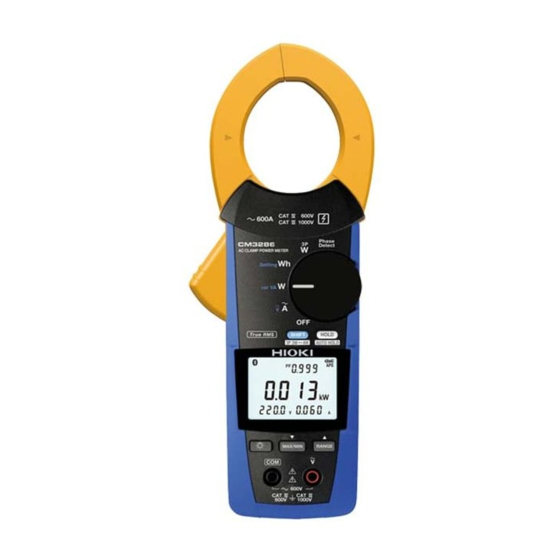
Introduction Introduction Thank you for purchasing the Hioki CM3286/CM3286-01 AC Clamp Power Meter. To obtain maximum performance from the instrument over the long term, be sure to read this manual carefully and keep it handy for future reference. This clamp power meter provides functionality for measuring AC current, voltage, power, and frequency as well as for detecting phase. - Page 6 When you receive the instrument, inspect it carefully to ensure that no damage occurred during shipping. In particular, check the accessories, panel switches, and connectors. If damage is evident, or if it fails to operate according to the specifications, contact your authorized Hioki distributor or reseller.
- Page 7 • Bluetooth is a registered trademark of Bluetooth SIG, Inc.(USA). The trademark is used by HIOKI E.E. CORPORATION under license. • Android and Google Play are trademarks of Google, Inc. • IOS is a registered trademark of Cisco in the U.S. and other countries.
-
Page 8: Options (Sold Separately)
9243 graber 9243 graber L4937 マグネットアダプ L4937 マグネットアダプ タ タ 9243 graber L4937 マグネットアダプ DM4910 熱電対 9243 graber DM4910 熱電対 L4937 マグネットアダプ タ タ DM4910 熱電対 DM4910 熱電対 L4934 小ワニグチ L4934 小ワニグチ DT4911TestLead DT4911TestLead DT4912TestLead L4934 小ワニグチ DT4912TestLead DT4911TestLead マグネ付ストラップ マグネ付ストラップ... -
Page 9: Safety Notes
Safety Notes Safety Notes This instrument is designed to conform to IEC 61010 Safety Standards, and has been thoroughly tested for safety prior to shipment. However, using the instrument in a way not described in this manual may negate the provided safety features. Before using the instrument, be certain to carefully read the following safety notes. - Page 10 Safety Notes WARNING Protective gear This instrument is measured on a live line. To prevent an electric shock, use appropriate protective insulation and adhere to applicable laws and regulations. Notation In this document, the risk seriousness and the hazard levels are classified as follows. Indicates information related Indicates an imminently to the operation of the...
- Page 11 Safety Notes Symbols affixed to the instrument Indicates cautions and hazards. When the symbol is printed on the Indicates AC (Alternating Current). instrument, refer to a corresponding topic in the Instruction Manual. Indicates that dangerous voltage may Indicates DC (Direct Current). be present at this terminal.
- Page 12 Safety Notes Measurement categories DANGER To prevent an electric shock, do not exceed the lower of the ratings shown on the instrument and connecting cords. Distribution panel Service entrance Internal wiring Service drop CAT II (≤1000 V) CAT III CAT IV (≤1000 V) (≤600 V) Outlet...
-
Page 13: Usage Notes
Usage Notes Usage Notes Follow these precautions to ensure safe operation and to obtain the full benefits of the various functions. DANGER • Do not use the instrument with circuits that exceed its ratings or specifications. Doing so may damage the instrument or cause it to become hot, resulting in bodily injury. - Page 14 Usage Notes DANGER • Do not short‑circuit two wires to be measured by bringing the clip or jaw tip of the connecting cords into contact with them. Arcs or such grave accidents are likely to occur. • To prevent an electric shock, be careful to avoid shorting live lines with the connecting cords tip.
- Page 15 Usage Notes WARNING • Installing the instrument in inappropriate locations may cause a malfunction of instrument or may give rise to an accident. Avoid the following locations. • Exposed to direct sunlight or high temperature • Exposed to corrosive or combustible gases •...
- Page 16 • To prevent instrument damage or an electric shock, use only the screw for securing the battery cover in place that is originally installed. If you have lost a screw or find that a screw is damaged, please contact your authorized Hioki distributor or reseller for replacement.
- Page 17 Usage Notes CAUTION • To avoid damage to the instrument, protect it from physical shock when transporting and handling it. Be especially careful to avoid physical shock due to dropping it. • Do not place foreign objects between jaws or insert foreign objects into the gaps of the sensor head.
- Page 18 Usage Notes Current measurement precautions Do not clamp Do not touch. around two wires. Do not input Do not pinch wire excessively high between jaws. currents or voltages. (Flashes red) 1.800.561.8187 information@itm.com www. .com...
-
Page 19: Part Names
Part Names Part Names (CM3286-01) Front Rear Battery cover (p. 1 2) Barrier* Lever Rotary switch HOLD L9257 Connection Cord Connector SHIFT Alligator clip Cord (Selects function indicated in (p. 8 ) blue lettering.) Operation keys Voltage input terminal Barrier* Sleeve (p. ... -
Page 20: Operation Keys
Count down (when setting meter constants) p. 4 6 – meter constants) MAX/MIN Enables/disables external ® Toggles the display backlight on and off p. 5 5 communications (Bluetooth ) (only p. 5 9 for CM3286-01, setting is stored) 1.800.561.8187 information@itm.com www. .com... -
Page 21: Rotary Switch
Operation keys Rotary switch When functions other than is selected, the instrument turns on. Select the desired function. "Phase Detection [Phase Detect]" (p. 38) • "AC 3-phase measurement (3P3W, balanced) [3PW]" (p. 31) • "AC 3-phase measurement (3P3W, unbalanced) [3PW]" (p. 32) •... -
Page 22: Power-On Option Table (Buzzer Sound, Resetting The Instrument To The Factory Settings, Etc.)
Operation keys Power‑on Option Table (buzzer sound, resetting the instrument to the factory settings, etc.) Turn on the power while pressing the operation key. (Turn the rotary switch from OFF.) Factory Setting Setting Operating instruction setting retained? Switching the auto power save –... - Page 23 Operation keys Factory Setting Setting Operating instruction setting retained? Selecting the CT ratio p. 5 6 Reset to the factory setting – – – 1.800.561.8187 information@itm.com www. .com...
-
Page 24: Insert / Replace Batteries
Insert / Replace Batteries Insert / Replace Batteries Fully charged. As the battery charge diminishes, black charge bars disappear, one by one, from the left of the battery indicator. The battery voltage is low. Replace the batteries as soon as possible. The instrument may lose power when the backlight turns on, when a buzzer sounds, etc. -
Page 25: Inspection Before Measurement
Inspection Before Measurement Verify that the instrument operates normally to ensure that no damage occured during storage or shipping. If you find any damage, contact your authorized Hioki distributor or reseller. Check item The battery cover is closed and its screw ... -
Page 26: Screen / Basic Operation
Screen / Basic Operation Screen / Basic Operation Setting the rotary switch to a position other than causes the instrument to turn on and the screen to activate. e.g.: During balanced 3-phase 3-wire active power measurement Connection display Measurement display Displays the connection locations for 3-phase Displays the measured value. -
Page 27: Screen Display
® Appearing: Bluetooth communications function enabled Flashing: Bluetooth ® communications active (only for CM3286-01) Connection type (not shown during single- phase measurement) Unbalanced mode operation (not shown during balanced mode operation) Manual range operation (not shown during auto-range operation) (All indicators displayed) -
Page 28: Switching The Information Shown On The Measurement Display
Screen / Basic Operation Switching the information shown on the measurement display Able to switch using the SHIFT key (Excluding the functions). How to use this chart: (Sub1 display) FREQ Sub1 display (Main display) (Sub2 display) (Sub3 display) Main – display |PEAK| Current... - Page 29 Screen / Basic Operation Active power Apparent power Reactive power Power factor Zero-cross phase angle Rotary switch (Main display) Voltage/Power factor φ PF * PF * PF * Balance φ mode* φ Unbalance – mode* φ φ P : Single-phase active power : Active power 1 : Active power 2 : Active power 3...
- Page 30 Screen / Basic Operation : Balanced 3-phase active power : Unbalanced 3-phase active power : Balanced 3-phase apparent power : Unbalanced 3-phase apparent power : Balanced 3-phase reactive power : Unbalanced 3-phase reactive power : Balanced 3-phase power factor : Unbalanced 3-phase power factor φ: Zero-cross phase angle φ...
-
Page 31: Connecting The Clamp And Clips
Connecting the Clamp and Clips Connecting the Clamp and Clips Clamp Clip (Alligator) Connect to metal part. Clip (Magnetic adapter) Connect to metal part. Align the current direction mark with the direction of the current. (If unable to connect the magnetic adapter so that it sits perpendicular to the terminal due to the weight of the voltage cord, connect it at an angle so as to balance it against the weight of the cord.) -
Page 32: Current/Voltage Measurement (Frequency)
Current/Voltage Measurement (Frequency) [ Current/Voltage Measurement (Frequency) Current measurement L/R/A Clamp Measurement display* Voltage measurement "Switching the information shown on the measurement display" (p. 24) L/R/A If the screen turns red: Clip "Warning display" (p. 67) Black The frequency display flashes Measurement when frequency exceeds display*... -
Page 33: Power Measurement (Power/Power Factor)
Power Measurement (Power/Power Factor) Power Measurement (Power/Power Factor) AC single‑phase measurement (1P2W) [var VA W] Clamp and clip L/R/A Black Measurement display* "Switching the information shown on the measurement display" (p. 24) If the screen turns red: "Warning display" (p. 67) 1.800.561.8187 information@itm.com www. -
Page 34: Ac Single-Phase Measurement (1P3W) [Var Va W]
Power Measurement (Power/Power Factor) AC single‑phase measurement (1P3W) [var VA W] Clamp and clip Black Black Clamp and clip "Switching the information shown on Measurement display* the measurement display" (p. 24) If the screen turns red: "Warning display" (p. 67) 1.800.561.8187 information@itm.com www. -
Page 35: Ac 3-Phase Measurement (3P3W, Balanced) [3Pw]
Power Measurement (Power/Power Factor) AC 3‑phase measurement (3P3W, balanced) [3PW] Clamp and clip L1/R/A Black Connection display (p. 2 2) L2/S/B L3/T/C Measurement display (calculation result)* "Switching the information shown on the measurement display" (p. 24) If the screen turns red: "Warning display"... -
Page 36: Ac 3-Phase Measurement (3P3W, Unbalanced) [3Pw]
Power Measurement (Power/Power Factor) AC 3‑phase measurement (3P3W, unbalanced) [3PW] Clamp and clip L1/R/A Clamp Connection display 1 (p. 2 2) and clip Black Black L2/S/B L3/T/C To next • Proceed to the next step after page verifying that the measured Measurement display values shown on measurement (active power 1) - Page 37 Power Measurement (Power/Power Factor) Measurement display Measurement display (calculation result) (active power 2) (3-phase active power) When the active power is negative, “ − ” appears beside it. Displays alternately 3-phase active power Active power 1 Active power 2 Long press The measured value is cleared and returns to the initial connection display.
-
Page 38: Ac 3-Phase Measurement (3P4W, Balanced) [3Pw]
Power Measurement (Power/Power Factor) AC 3‑phase measurement (3P4W, balanced) [3PW] Clamp and clip Red L1/R/A L2/S/B L3/T/C Black More than 1 sec. Measurement display Connection display (p. 2 2) (calculation result)* If the screen turns red: "Warning display" (p. 67) "Switching the information shown on the measurement display"... -
Page 39: Ac 3-Phase Measurement (3P4W, Unbalanced) [3Pw]
Power Measurement (Power/Power Factor) AC 3‑phase measurement (3P4W, unbalanced) [3PW] Clamp and clip Clamp L1/R/A and clip L2/S/B L3/T/C More than 1 sec. Black Connection display 1 (p. 2 2) Black To next page Measurement display 1 Connection display 2 (active power 1) Proceed to the next step after verifying that the measured values... - Page 40 Power Measurement (Power/Power Factor) Measurement display 2 (active power 2) Clamp L1/R/A and clip L2/S/B L3/T/C Black Connection display 3 Measurement display 3 (active power 3) Proceed to the next step after To next page verifying that the measured values shown on measurement displays 2 and 3 are normal.
- Page 41 Power Measurement (Power/Power Factor) Measurement display 4 (calculation result) (3-phase active power) Active power 3 3-phase active power Displays Active power 2 alternately Active power 1 When the active power is negative, “ − ” appears beside it. Long press The measured value is cleared and returns to the initial connection display.
-
Page 42: Phase Detection [Phase Detect]
Phase Detection [Phase Detect] Phase Detection [Phase Detect] Clip L1/R/A Clip* Connection display (p. 2 2) L2/S/B Black Black L3/T/C • The instrument will display To next page “– – – –” if open phase is detected or if it is unable to make a Connection display Measurement display measurement. - Page 43 Phase Detection [Phase Detect] Measurement display Reverse phase Normal phase Display appears in the order of the arrow. Display of results Line voltage (2 measurement) (Lights red) Goes back to the first display when the HOLD key is pressed. 1.800.561.8187 information@itm.com www.
-
Page 44: Single-Phase Active Energy Measurement (Integrated Measurement) [Setting Wh]
Single-phase Active Energy Measurement (Integrated Measurement) [Setting Wh] Single‑phase Active Energy Measurement (Integrated Measurement) [Setting Wh] Clamp and clip L/R/A Set the constant number to OFF. Black To next page 1.800.561.8187 information@itm.com www. .com... - Page 45 Single-phase Active Energy Measurement (Integrated Measurement) [Setting Wh] Set the instrument to power integration mode. • Range is fixed when integration Start integration. starts. Change the range before starting to integrate a large power quantity or for an extended period of time. •...
-
Page 46: Single-Phase Energy Meter Comparison Function [Setting Wh]
Single-phase Energy Meter Comparison Function [Setting Wh] Single‑phase Energy Meter Comparison Function [Setting Wh] This function allows you to compare the actual energy value (measured value) from an energy meter with the theoretical value. There are two ways to start and stop integration: •... - Page 47 Single-phase Energy Meter Comparison Function [Setting Wh] 1‑cycle mode Mechanical meter Electronic meter Once the disc has completed one revolution When the LED flashes once Start integration Start integration Disc Stop integration Stop integration Fixed energy mode e.g.: With the fixed energy set to 0.1 kWh Start integration 0.1 kWh digit Stop integration...
- Page 48 Single-phase Energy Meter Comparison Function [Setting Wh] Clamp and clip L/R/A Select the constant number or fixed energy*. Black To next page * Select fixed energy mode if the energy meter’s disc rotates, or if its LED flashes, quickly. The constant can be changed. "Watt-hour meter constants default setting value"...
- Page 49 Single-phase Energy Meter Comparison Function [Setting Wh] Set the instrument to power Single-phase active power (measured value) integration mode. Start integration. Elapsed time Energy (theoretical value) • Only the positive (consumption) active power is added. Negative (generation) active power is not added. •...
-
Page 50: Setting The Desired Meter Constant
Single-phase Energy Meter Comparison Function [Setting Wh] Setting the desired meter constant Set after conducting the procedures 1 and 2 of "Single-phase Energy Meter Comparison Function [Setting Wh]" (p. 42) The selected portion will flash. Select the portion you wish to change. Change the value. - Page 51 Single-phase Energy Meter Comparison Function [Setting Wh] Watt‑hour meter constants default setting value No.01 to No.10: 1-cycle mode 0.10 kWh to 0.01 kWh: Fixed energy mode Changing the Changing the setting value setting value SET No. Setting value SET No. Setting value Enable: ...
-
Page 52: Manual Hold / Auto Hold
Manual Hold / Auto Hold Manual Hold / Auto Hold MANUAL HOLD AUTO HOLD To measurement object → flashes. Press for 1 sec. To measurement object (Measured value > stabilizes.) Measured value is retained. appears) Measured value is Disconnect automatically retains. Pressing the HOLD key again cancels... - Page 53 Manual Hold / Auto Hold Auto hold conditions Measured value is automatically retained when the following two conditions are satisfied: • When the range over which the measured value is fluctuating stabilizes within the fluctuation range described in the table in the next page. •...
- Page 54 Manual Hold / Auto Hold Measurement Fluctuation range Threshold value function* AC current Current RMS value Current RMS value 6.000 A range: within 60 counts 6.000 A range: 59 counts 60.00 A range: within 60 counts 60.00 A range: 59 counts 600.0 A range: within 60 counts 600.0 A range: 59 counts AC voltage...
-
Page 55: Switching Ranges
Switching Ranges Switching Ranges e.g.: During current measurement AUTO range MANUAL 600.0 A range MANUAL 60.00 A range MANUAL 6.000 A range 1.800.561.8187 information@itm.com www. .com... -
Page 56: Max/ Min/ Avg
MAX/ MIN/ AVG MAX/ MIN/ AVG To measurement object Present value : To switch the main display. (long press) or (switching functions): MAX/MIN/AVG measurement function is cleared. • Switches to manual range when it is auto range. ( appears) • The MAX/MIN/AVG measurement will be continued during hold function. •... - Page 57 MAX/ MIN/ AVG During current measurement e.g.: Maximum measured value of the current RMS* Maximum measured value's time* *1 The maximum, minimum, and average values for the main display’s measured value is shown. (However, only the maximum and average values are shown during peak value measurement. Also, only the maximum and minimum values are shown during zero-cross phase angle measurement.) *2 Measured value's update time is displayed when maximum or minimum value is shown.
- Page 58 MAX/ MIN/ AVG |PEAK| Waveform Measured value (RMS value) MAX/MIN/AVG of the RMS value |PEAK| Display refresh interval AVG: Average value after pressing the MAX/MIN MAX: Maximum value after pressing the MAX/MIN MIN: Minimum value after pressing the MAX/MIN |PEAK|: Maximum value of the absolute value of the waveform during the display update interval 1.800.561.8187 information@itm.com www.
-
Page 59: Backlight / Auto Power Save (Aps)
Backlight / Auto Power Save (APS) Backlight / Auto Power Save (APS) (Ordinarily on) Backlight Auto power save (APS) Switching the function: p. 1 8 Backlight OFF Power OFF 30 sec. before Flashes No input and Power OFF 10 sec. before operation for approx. -
Page 60: Measurement Using The Clamp Adapter
Measurement Using the Clamp Adapter Measurement Using the Clamp Adapter A clamp adapter (sold separately) can be used to measure currents that are larger than the rated input current. Rotary switch CT ratio Select the CT ratio. 1/1 (not shown) 1/10 1/100 1/1000... -
Page 61: Bluetooth ® Communications (Only For Cm3286-01)
Install the GENNECT Cross on your mobile device. (p. 5 8) Enable the Bluetooth ® function on the CM3286‑01. (p. 5 9) Press for 1 Launch the GENNECT Cross and pair it with the CM3286‑01. sec. (p. 6 0) Select the General... -
Page 62: Installing The Application Software Gennect Cross
• Because the CM3286-01 emit radio waves, use in a country or region where they have not been approved may be subject to fines or other penalties as a violation of applicable laws or regulations. For more information, see the attached “Precautions Concerning Use of Equipment That Emits Radio Waves”... -
Page 63: Turning On The Bluetooth ® Function
® Bluetooth Communications (only for CM3286-01) ® Turning on the Bluetooth function ® ® Bluetooth function OFF Bluetooth function ON Press for 1 sec. icon will flash when the instrument is connected to a mobile device. 1.800.561.8187 information@itm.com www. .com... -
Page 64: Pairing The App With The Cm3286-01
• While the mobile device is displaying the Instrument Settings screen, simply move it close to a CM3286- 01 to automatically pair it with the instrument (the app can be paired with up to 8 instruments). • Allow about 5 to 30 seconds for the instrument to pair with the app after being turned on. If the instrument fails to pair within 1 minute, relaunch GENNECT Cross and cycle the instrument’s power. -
Page 65: Making Measurements With The Bluetooth ® Function
® Bluetooth Communications (only for CM3286-01) ® Making measurements with the Bluetooth function General Measurement, Logging (Recording), Waveform Graph, Electricity Theft Detection, Select the Harmonic Analysis Home Help function on the screen. For more information about each function, see the function in the GENNECT Cross. - Page 66 Bluetooth® Communications (only for CM3286-01) Electricity Theft Detection Harmonic Analysis Creates a result report by measuring current and Analyzes levels, content percentages, and total energy. distortion (voltage, current). 1.800.561.8187 information@itm.com www. .com...
-
Page 67: Repairs, Inspections, And Cleaning
Repairs, Inspections, and Cleaning Repairs, Inspections, and Cleaning WARNING Customers are not allowed to modify, disassemble, or repair the instrument. Doing so may cause a fire, an electric shock, or a injury.. Cleaning • To clean the instrument, wipe it gently with a soft cloth moistened with water or mild detergent. •... - Page 68 The calibration period varies depending on the status of the instrument or installation environment. We recommend that the calibration period be determined in accordance with the status of the instrument or installation environment. Please contact your Hioki distributor to have your instrument periodically calibrated.
-
Page 69: Troubleshooting
Troubleshooting Troubleshooting If damage is suspected, check the following before contacting your authorized Hioki distributor or reseller. Symptom Verification and/or Solution • The instrument is indicating an • Is the measured current value too small for the instrument’s abnormal measured value for measurement range? current. - Page 70 Troubleshooting Symptom Verification and/or Solution • The current value is larger than • The instrument cannot perform measurement accurately in the expected. presence of a strong magnetic field from a source such as a nearby • A current value is displayed even transformer or high-current circuit or in the presence of a strong though there is no input.
- Page 71 ROM error Program Err 002 ROM error Adjustment data Repair is necessary. Please contact your Err 005 ADC error Hardware malfunction authorized Hioki distributor or reseller. Bluetooth ® Hardware malfunction Err 008 error (only for CM3286-01) Warning display Display Buzzer...
- Page 72 Troubleshooting Display Buzzer Cause Solution Stop measurement immediately as the current or voltage cannot be measured by the instrument. For current A current or voltage measurement, the optional Flashes Intermittent exceeding the maximum 9290-10 can be used to sound input was input to the measure currents of up to instrument.
- Page 73 Troubleshooting Display Buzzer Cause Solution Lights Intermittent Phase detection sound indicated reverse phase. 1.800.561.8187 information@itm.com www. .com...
-
Page 74: General Specifications
Specifications Specifications General Specifications Operating environment Indoors, pollution degree 2, altitude up to 2000 m (6562 ft.) Operating temperature Temperature −25°C (−13°F) to 65°C (149°F) and humidity Humidity −25°C (−13°F) or higher but less than 40°C (104°F): 80% RH or less 40°C (104°F) or higher but less than 45°C (113°F): 60% RH or less 45°C (113°F) to 65°C (149°F): 50% RH or less... -
Page 75: Specifications
23°C, as a referential) Interface (only for Bluetooth ® 4.0LE ( CM3286-01) Dimensions Approx. 82W × 241H × 37D mm (3.23″W × 9.49″H × 1.46″D) Jaw dimensions Approx. 79W × 20D mm (3.11″W × 0.79″D) Maximum measurable 46 mm (1.81″) - Page 76 Specifications Input/Output/Measurement Specifications Basic Specifications Measurement items AC current RMS value/AC current peak value (no polarity)/AC current frequency AC voltage RMS value/AC voltage peak value (no polarity)/AC voltage frequency Single-phase active power/Single-phase apparent power/Single-phase reactive power/Single-phase power factor/Single-phase zero-cross phase angle Balanced 3-phase active power/Balanced 3-phase reactive power/Balanced 3-phase apparent power/Balanced 3-phase power factor/Balanced 3-phase zero-cross phase angle...
-
Page 77: Input/Output/Measurement Specifications
Specifications Display update interval 2 times/sec. Response time 1 sec. Crest factor 3 or less for current 6 A and 60 A range 1.6 or less for current 600 A range and voltage 600 V range Zero-display range • Voltage and current RMS values: 29 counts or less •... - Page 78 Conditions of Guaranteed accuracy period: 1 year guaranteed accuracy Guaranteed accuracy period after adjustment made by Hioki: 1 year Guaranteed accuracy for temperature and humidity: 23°C±5°C (73°F±9°F), 80% RH or less (no condensation) Number of jaw open/close cycles: 10000 times or less...
- Page 79 Specifications Harmonic Measurement Specifications (only for CM3286-01) All operations are performed by the GENNECT Cross application software. The following specifications apply only to use of the GENNECT Cross’s harmonic analysis functionality. Perform sampling of data by instrument and harmonic analysis calculations by GENNECT Cross.
-
Page 80: Harmonic Measurement Specifications (Only For Cm3286-01)
Specifications Range (maximum AC current 600.0 A 60.00 A 6.000 A resolution) (0.1 A) (0.01 A) (0.001 A) AC voltage 600.0 V (0.1 V) Accuracy input range Input of 1% of range or greater for each order Crest factor 3 or less for the 6 A and 60 A current ranges 1.6 or less for the 600 A current range and the 600 V voltage range Data refresh 5 s (reference value) -
Page 81: Application Software Specifications
Specifications ® External Interface (Bluetooth ) Specifications Display function Display of measured values on a iOS device or a Android device, using ® Bluetooth communications. Interface Bluetooth ® 4.0 LE Antenna power Maximum +0 dBm (1 mW) Communications range 10 m (line of sight) Communications GATT (Generic Attribute Profile) profile... -
Page 82: External Interface (Bluetooth ® ) Specifications
Accuracy Table Accuracy Table AC Current Measurement The current RMS (I ) and current peak value (I ) ranges will change at the same time. |PEAK| Auto range threshold: Range up: Current RMS value greater than 6000 count Range down: Current RMS value less than 540 count AC current RMS Resolution Accuracy... -
Page 83: Accuracy Table
Accuracy Table AC current peak Range Resolution Accuracy value (I (Accuracy guarantee |PEAK| Zero to Peak range is specified in 45 Hz ≤ f ≤ 66 Hz < f ≤ 500 Hz < f ≤ Display range terms of current RMS 66 Hz 500 Hz 1 kHz... - Page 84 Accuracy Table AC Voltage Measurement AC voltage RMS Resolution Accuracy Range value (U (Accuracy guarantee 45 Hz ≤ f ≤ 66 Hz < f ≤ 500 Hz < f ≤ Display range range) 66 Hz 500 Hz 1 kHz 0.1 V 600 V ±0.7% rdg.
- Page 85 Accuracy Table AC voltage Resolution Accuracy Range frequency Voltage frequency values are shown as “– – – –” (Accuracy guarantee (FREQ Maximum when the voltage RMS value is less than 150 count. Voltage frequency values of less than range) display 45.0 Hz are shown as “–...
- Page 86 Accuracy Table Single-phase Range configuration (minimum resolution) Current range active power/ 6.000 A 60.00 A 600.0 A Balanced Voltage range 600.0 V Single- 3.600 kW 36.00 kW 360.0 kW 3-phase/4-wire phase (0.001 kW) (0.01 kW) (0.1 kW) active power (P / P 3-Phase 10.80 kW 108.0 kW...
- Page 87 Accuracy Table Single-phase Accuracy ±1 dgt. relative to calculation from measured values power factor/ Range configuration Regeneration −1.000 to −0.001 Balanced Consumption 0.000 to 1.000 3-phase/4-wire power factor (PF / PF (3P4W) Zero-cross phase Accuracy ±3° angle (φ)* Range configuration Lead −180.0°...
- Page 88 Accuracy Table Balanced Accuracy ±3.0% rdg. ±10 dgt. (Power factor =1) 3-phase/3- Range Current range wire active configuration 6.000 A 60.00 A 600.0 A power (P (minimum (3P3W) 7.200 kW 72.00 kW 720.0 kW resolution) Voltage range 600.0 V Balanced (0.001 kW) (0.01 kW) (0.1 kW)
- Page 89 Accuracy Table * Value is calculated based on the measurement of the zero-cross phase difference for the voltage and current waveforms (positive [no sign] when the current lags the voltage and negative when the current leads the voltage). Single-phase active energy measurement (AC) Effective Current RMS value (I 0.060 A to 600.0 A...
- Page 90 Accuracy Table Single-phase Measurement method Positive active power values are added every 0.5 s.* active energy A value of zero is added when the active power is (Wh) negative. * When stopping integration, the energy measured during the last 0.5 sec. is divided into 5 and added every 0.1 sec.
- Page 91 Accuracy Table Integration 59:59 [min:sec] The time is incremented by 1 s from 00:00 [min:sec]. time display When 59:59 [min:sec] is exceeded, the range is 48:00 [hour:min] switched to the 48:00 [hour:min] range. During integration using the 48:00 [hour:min] range, the “...
- Page 92 Accuracy Table Range configuration when setting a CT ratio CT ratio 1/10 1/100 1/1000 Remarks (default value) CT ratio 1/1 Same accuracy 600.0 A 6000 A – – specifications as 600.0 A. Current RMS CT ratio 1/1 Same accuracy 60.00 A 600.0 A 6000 A –...
- Page 93 Accuracy Table CT ratio 1/10 1/100 1/1000 Remarks (default value) CT ratio 1/1 Same accuracy 720.0 kW 7200 kW – – specifications as 720.0 kW. Balanced CT ratio 1/1 Same accuracy 3-phase/3-wire 72.00 kW 720.0 kW 7200 kW – specifications as 72.00 kW. active power CT ratio 1/1 Same accuracy 7.200 kW...
- Page 94 Equations Equations Single-phase power measurement ・ I Apparent power • The active power P has no sign during consumption and a negative sign during Reactive power S − generation. • Due to the effects of measurement error, Power factor S=|P| and Q=0 are used when S<|P|. Balanced 3-phase/3-wire power measurement Balanced 3-phase/3-wire φ...
-
Page 95: Equations
Equations Balanced 3-phase/4-wire power measurement • The symbol P represents the active power of Balanced 3-phase/4-wire (3P4W) ・ P the phase voltage U and the wire current I active power • The symbol S represents the apparent power of Balanced 3-phase/4-wire (3P4W) ・... - Page 96 Equations Unbalanced 3-phase/4-wire power measurement • The symbol P represents the active power of the phase voltage U and the wire current I • The symbol P represents the active power of the Unbalanced 3-phase/4-wire phase voltage U and the wire current I (UB3P4W) active power •...
- Page 97 Equations • The symbol Q represents the reactive power of the phase voltage U and the wire current I • The symbol Q represents the reactive power of the Unbalanced 3-phase/4-wire phase voltage U and the wire current I (UB3P4W) reactive power [var] •...
- Page 98 Equations (Reference) Harmonic calculations Calculated by GENNECT Cross RMS value – Harmonic content × percentage for k th order – ∑ Harmonic current THD-F × Total harmonic distortion ∑ × THD-R ∑ 1.800.561.8187 information@itm.com www. .com...
- Page 99 Equations RMS value – Harmonic content × percentage for k th order – ∑ Harmonic voltage THD-F × Total harmonic distortion ∑ × THD-R ∑ Index k: Analyzed order r: Post-FFT resistance component i: Post-FFT reactance component I’: Current sampling value U’: Voltage sampling value 1.800.561.8187 information@itm.com...
- Page 100 1.800.561.8187 information@itm.com www. .com...
Need help?
Do you have a question about the CM3286 and is the answer not in the manual?
Questions and answers