
Related Manuals for Hioki CM4375


Summary of Contents for Hioki CM4375
- Page 1 CM4375 Instruction Manual CM4376 AC/DC CLAMP METER Sept. 2018 Edition 1 CM4375A961-00 18-09H...
-
Page 3: Table Of Contents
Contents Introduction ..................... 1 Notation ......................2 Verifying Package Contents ................4 Options (sold separately)................5 Usage Notes ....................6 Overview Product Overview and Features ............11 Part Names ..................12 Making Measurements Inspection Before Measurement ............13 Current Measurement ................ 14 Manual Hold / Auto Hold .............. - Page 4 Contents Backlight / Auto Power Save (APS) ............. 30 Power-on Option Table ............... 31 Specifications 3.1 General Specifications ............... 33 3.2 Input specifications/Measurement specifications ....... 35 Accuracy Table ................... 42 Repairs, Inspections, and Cleaning Troubleshooting .................. 57 Error display ..................59 Insert/Replace Batteries ..............60 Cleaning .....................
-
Page 5: Introduction
Introduction Thank you for purchasing the Hioki CM4375, CM4376 AC/DC Clamp Meter. To obtain maximum performance from the instrument over the long term, be sure to read this manual carefully and keep it handy for future reference. Read the separate document “Operating Precautions” carefully before using the instrument. -
Page 6: Notation
Notation Notation Symbols affixed to the instrument Indicates cautions and hazards. Refer to the "Usage Notes" (p. 6) section of the instruction manual and the included “Operating Precautions” for more information. Indicates that the instrument may be connected to or disconnected from a live conductor. Screen display The instrument screen displays the alphanumeric characters as follows. - Page 7 Notation Accuracy We define measurement tolerances in terms of f.s. (full scale), rdg. (reading) and dgt. (digit) values with the following meanings: f.s. (maximum display value/range) The maximum displayable value. This is usually the name of the currently selected range. rdg.
-
Page 8: Verifying Package Contents
DT4911TestLead Verifying Package Contents DT4912TestLead マグネ付ストラップ Verifying Package Contents L4930 接続ケーブル Model CM4375 or CM4376 Model L9207-10 Test Lead AC/DC Clamp Meter L9207-10 Model C0203 Carrying Case L4931renketu L4931 延長ケーブル L4932(+9207-10cap) LR03 Alkaline battery ×2 Instruction Manual* ... -
Page 9: Options (Sold Separately)
タ DM4910 熱電対 L4930 接続ケーブル L9207-10 L9207-10 Options (sold separately) L4931renketu DM4910 熱電対 L4931renketu L4931 延長ケーブル マグネ付ストラップ L9207-10 Options (sold separately) L4931 延長ケーブル L4934 小ワニグチ L4931renketu 9243 graber DT4911TestLead L4937 マグネットアダプ L4932(+9207-10cap) ブル L4934 小ワニグチ タ L4931 延長ケーブル L4932(+9207-10cap) DT4911TestLead DM4910 熱電対... -
Page 10: Usage Notes
Usage Notes Usage Notes Follow these precautions to ensure safe operation and to obtain the full benefits of the various functions. Read the separate document “Operating Precautions” carefully before using the instrument. Ensure that your use of the product falls within the specifications not only of the instrument itself, but also of any accessories, options, batteries, and other equipment being used. - Page 11 Usage Notes WARNING • Do not allow the instrument to get wet, and do not take measurements with wet hands. This may cause an electric shock. (This precaution does not apply to insulated conductors.) • To prevent an electric shock, do not exceed the lower of the ratings shown on the instrument and test leads.
- Page 12 Usage Notes Test Lead WARNING To prevent an electric shock, when measuring the voltage of a power line use a test lead that satisfies the following criteria: • Conforms to safety standards IEC61010 or EN61010 • Measurement category III or IV •...
- Page 13 Usage Notes Model L4937, 9804 Magnetic Adapter Set (optional) DANGER Persons wearing electronic medical devices such as a pacemaker should not use the Magnetic Adapter Set. Such persons should avoid even proximity to the Magnetic Adapter Set, as it may be dangerous. Medical device operation could be compromised, presenting a hazard to human life.
- Page 14 Usage Notes...
-
Page 15: Overview
Overview 1.1 Product Overview and Features This instrument is a clamp meter that can Measurement function list perform true RMS measurement of current DC current/DC voltage, DC power simply by clamping it around a circuit. In addition to current, it provides voltage Capacitance, temperature measurement, frequency measurement, rush current measurement, resistance measurement,... -
Page 16: Part Names
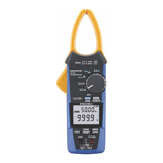
Overview 1.2 Part Names Front Rear Operation grip Jaw open/closed mark (The jaws are open if the mark is not showing.) SHIFT (Selects function indicated in blue lettering.) Barrier Serial number (The serial number consists of 9 digits. The first two (from the left) indicate the year of manufacture, and the next two indicate the month of manufacture.) Rotary switch... -
Page 17: Making Measurements
Check if there is any damage to the instrument occurred during storage or shipping and verify that instrument operates normally before using it. If you find any damage, contact your authorized Hioki distributor or reseller. Check item The battery cover is closed and its screw has There is no damage to the test lead ... -
Page 18: Current Measurement
Current Measurement 2.2 Current Measurement Turn the rotary switch. Clamp the instrument around a conductor. e.g.: 3P4W (3-phase, 4-wire) circuit breaker (AC current measurement) Press for 1 sec. Zero adjustment Be sure that the currents direction points the arrow. Frequency detection range of AC current 5.0 A or more DC current polarity detection function... -
Page 19: Manual Hold / Auto Hold
Current Measurement Manual Hold / Auto Hold Manual hold Auto hold blinks. Press for 1 sec. Clamp the instrument around a conductor. Measured value retains. (Measured value stabilizes.) Pressing the HOLD key again cancels the measured value hold function. Disconnect Measured value automatically retains. - Page 20 Current Measurement Auto hold conditions Display value updates are stopped when the following two conditions are satisfied: • When the measured value exceeds the threshold value described in the table in the next page. (voltage, current). When the measured value is less than the threshold value described in the table in the next page. (resistance, continuity, diode) •...
- Page 21 Current Measurement Measurement function Fluctuation range Threshold value AUTO A Within 120 counts 120 counts AC current DC current AC+DC current AC voltage 6.000 V/60.00 V/600.0 V range: 6.000 V/60.00 V/600.0 Vrange: DC voltage within 120 counts 120 counts (excluding the 600.0 mV range) 1000 V range: within 20 counts 1000 V range: 20 counts AC+DC voltage...
-
Page 22: Filter Function
Current Measurement Filter Function FILTER OFF FILTER ON Measured value including noise Measured value with reduced noise Press for 1 sec. Frequency characteristics when using the Turn off the filter function when performing filter function (100 A input) measurement of power supply frequencies in excess of 100 Hz, for example on an aircraft or ship. -
Page 23: Max Value/Min Value/Avg Value/Peak Value
Current Measurement MAX value/MIN value/AVG value/PEAK value Clamp the instrument around a conductor. AUTO Can not be used at (AC A) (DC A) (AC+DC A) (Frequency) (AUTO AC/DC) AUTO AC/DC. Press for 1 sec. Cancel Measured value retains. PEAK MAX Waveform The instrument performs true RMS... -
Page 24: Rush Current (Inrush)
Current Measurement Rush current (INRUSH) Press for 1 sec. Turn off the motor. Turn the rotary switch. INRUSH ON (Rush current Turn on the motor. occurrence) Press for 1 sec. Zero adjustment RMS value (INRUSH) Clamp the instrument around a Example conductor. -
Page 25: Other Measurement Functions
Other Measurement Functions 2.3 Other Measurement Functions Voltage DC+AC成分の波形 e.g.: commercial power supply (AC voltage measurement) Switch the range DC成分の波形 AUTO (AUTO AC/DC) DC+AC成分の波形 AC成分の波形 (AC V) Black (DC V) DC成分の波形 (AC+DC V) AC成分の波形 DC+AC成分の波形 No overvoltage Do not touch. (Frequency) DC voltage polarity detection function (p. - Page 26 Other Measurement Functions Resistance Diode Continuity Check Zero adjustment Zero adjustment Press for 1 sec. Press for 1 sec. Black Black Black (Red display)
- Page 27 Other Measurement Functions Temperature Capacitance Black Model DT4910 Thermocouples (K) − Black : DT4910 is broken. To change the temperature display unit: p. 32 索 引...
- Page 28 Other Measurement Functions Simultaneous display of DC power DC current and DC voltage e.g.: Checking a car battery e.g.: Solar power system maintenance Black Black...
-
Page 29: Bluetooth ® Communications (Only For Cm4376)
® Bluetooth Communications (only for model CM4376) ® 2.4 Bluetooth Communications (only for model CM4376) The CM4376 are clamp-style meters with Bluetooth (Bluetooth low energy) support. When the Bluetooth function is enabled, you can review measurement data and create measurement reports on mobile devices (iPhone, iPad, iPad mini , iPad Pro, iPod touch, and Android devices). - Page 30 For more information, see the attached “Precautions Concerning Use of Equipment that Emits Radio Waves” or go to our website. • The CM4376 availability is limited to certain countries. For more information, contact your authorized Hioki distributor or reseller.
- Page 31 ® Bluetooth Communications (only for model CM4376) Turning on the Bluetooth function Bluetooth function OFF Bluetooth function ON Press for 1 sec. lights up: Bluetooth function ON flashes: Sending/receiving data 索 引...
- Page 32 ® Bluetooth Communications (only for model CM4376) Pairing the app with the CM4376 • When the app is launched for the first time (before being paired with any instrument), the Instrument Settings screen will be displayed. • While the mobile device is displaying the Instrument Settings screen, simply move it close to a CM4376 to automatically pair it with the instrument (the app can be paired with up to 8 instruments).
- Page 33 ® Bluetooth Communications (only for model CM4376) Making measurements with the Bluetooth function Select the General Measurement, Logging (Recording), or Waveform Graph function on the Home screen. For more information about each function, see the Help function in the GENNECT Cross. General Measurement Logging (Recording) Waveform Graph...
-
Page 34: Backlight / Auto Power Save (Aps)
Backlight / Auto Power Save (APS) 2.5 Backlight / Auto Power Save (APS) (Always on) Backlight Auto Power Save (APS) Cancelation method: (p. 31) Backlight OFF No operation for 15 min. You can turn the display back on by pressing a key or by turning the rotary switch. -
Page 35: Power-On Option Table
Power-on Option Table 2.6 Power-on Option Table Move the rotary switch from the “OFF” position to any of the test mode positions while pressing an operation key. Factory Setting Setting Operating instruction setting retained? Canceling the auto power save (APS) function (OFF) (Set each time) DC current and DC voltage polarity... - Page 36 Power-on Option Table Factory Setting Setting Operating instruction setting retained? Press for 1 sec. Switching the temperature unit °C To change the temperature unit: To save the setting: Press for 1 sec.
-
Page 37: Specifications
Specifications 3.1 General Specifications Operating environment Indoors, pollution degree 2, altitude up to 2000 m (6562 ft.) Operating temperature −25°C to 65°C (−13°F to 149°F), 90% RH or less (no condensation) and humidity Storage temperature −30°C to 70°C (−22°F to 158°F), 90% RH or less and humidity (no condensation, when batteries are removed) Dustproof and... - Page 38 General Specifications Dimensions Approx. 65W × 242H × 35D mm (2.56″W × 9.53″H × 1.38″D) (excluding protruding parts, operation grip, and jaw) Jaw dimensions Approx. 53W × 20D mm (2.09″W × 0.79″D) Jaw cross-sectional Approx. 9.5 mm (0.37″) minimum dimension Maximum measurable φ34 mm (1.34″) conductor diameter...
-
Page 39: Input Specifications/Measurement Specifications
Input specifications/Measurement specifications 3.2 Input specifications/Measurement specifications (1) Basic Specifications Measurement range See "3.3 Accuracy Table" (p. 42) Maximum rated voltage 1000 V AC (up to 1 kHz) to terminal 1700 V DC Maximum rated voltage 600 V AC (Measurement category IV) to earth 1000 V AC (Measurement category III) Anticipated transient overvoltage: 8000 V... - Page 40 Input specifications/Measurement specifications Display update rate * AUTO A/AC current/DC current/ 5 times/sec. AC+DC current Current frequency 0.3 times to 5.0 times/sec. (varies depending on the frequency.) DC power 1 time/sec. DC current+DC voltage 2.5 times/sec. Zero-display range AUTO A/AC current/DC current/ 5 counts or less AC+DCcurrent Crest factor...
- Page 41 Input specifications/Measurement specifications Frequency derating characteristics Frequency [Hz] (3) Voltage measurement specifications Overload protection 1870 V DC Lower of 1100 V AC or 2×10 V · Hz (Applied continuously for up to 1 min.) Coupling type AC voltage * AC coupling Other voltage measurements DC coupling than the above...
- Page 42 Input specifications/Measurement specifications Display update rate * AUTO V/AC voltage/ 5 times/sec. DC voltage/AC+DC voltage Voltage frequency 0.3 times to 5.0 times/sec. (varies depending on the frequency.) DC power 1 time/sec. DC current+DC voltage 2.5 times/sec. Zero-display range AUTO V/AC voltage/ 5 counts or less AC+DC voltage Crest factor...
- Page 43 Input specifications/Measurement specifications *1: Does not apply to AC detection in AUTO V mode. *2: Does not include range change time. Ω *3: Defined for 1 k unbalance, 0 Hz/50 Hz/60 Hz input *4: Defined for 50 Hz/60 Hz input (4) Other Measurement Specifications Overload 1700 V DC...
- Page 44 Input specifications/Measurement specifications Maximum capacity 10 mF load Maximum inductive 10 H load Instrument Up to 120 minutes (Reference: For an instrument at 23°C [ 73°F ] placed in a 65°C reference contact [ 149°F ] environment: 60 minutes) temperature correction stabilization time *1: Does not include range change time.
- Page 45 Guaranteed accuracy 1 year period after adjustment made by Hioki Guaranteed accuracy for 23°C±5°C (73°F±9°F), 90% RH or less (no condensation) temperature and humidity (Current/continuity check/resistance: after zero adjustment has been performed) (Use model DT4910 for temperature (Thermocouples [K])
-
Page 46: Accuracy Table
Accuracy Table 3.3 Accuracy Table (1) AUTO A (AC/DC current automatic detection) During AC detection: Conforms to accuracy specifications described in "(4) AC+DC current" (p. 44). During DC detection: Conforms to accuracy specifications described in "(3) DC current" (p. 43). (2) AC current Measurement value/MAX/MIN/AVE Measurement accuracy... - Page 47 Accuracy Table PEAK MAX/PEAK MIN Accuracy guarantee Accuracy guarantee range (Resolution) Measurement accuracy frequency range ±10 A to ±1000 A (1 A) 10 Hz ≤ f < 45 Hz ±1.8% rdg.±7 A 45 Hz ≤ f ≤ 66 Hz ±1.3% rdg.±7 A 66 Hz <...
- Page 48 Accuracy Table (4) AC+DC current Measurement value/MAX/MIN/AVE Measurement accuracy Accuracy guarantee Accuracy guarantee range (Resolution) frequency range Filter OFF Filter ON 1.0 A to 30.0 A (0.1 A) 10 Hz ≤ f < 45 Hz ±1.8% rdg.±1.2 A ±2.3% rdg.±1.2 A DC, 45 Hz ≤...
- Page 49 Accuracy Table (5) Current frequency/Voltage frequency Accuracy guarantee range Range (Auto-range threshold) Measurement accuracy (Resolution) 9.999 Hz (more than 9999 counts) 1.000 Hz to 9.999 Hz (0.001 Hz) ±0.1% rdg.±0.003 Hz 99.99 Hz (more than 9999 counts/ 1.00 Hz to 99.99 Hz (0.01 Hz) ±0.1% rdg.±0.01 Hz less than 900 counts) 999.9 Hz (less than 900 counts)
- Page 50 Accuracy Table (7) AUTO V (AC/DC voltage automatic detection) During AC detection: Conforms to accuracy specifications described in "(10) AC+DC voltage" (p. 51). During DC detection: Conforms to accuracy specifications described in "(9) DC voltage" (p. 49). (8) AC voltage Measurement value/MAX/MIN/AVE Range Accuracy...
- Page 51 Accuracy Table Range Accuracy Measurement accuracy Accuracy guarantee Input (Auto-range guarantee range frequency range * impedance * Filter OFF Filter ON threshold) (Resolution) Ω 60.00 V 3.00 V to 60.00 V 15 Hz ≤ f < 45 Hz ±1.5% rdg. ±2.0% rdg.
- Page 52 Accuracy Table PEAK MAX/PEAK MIN Accuracy guarantee range Accuracy guarantee Range Measurement accuracy (Resolution) frequency range * 6.000 V 0 V to ±12.00 V (0.01 V) 15 Hz ≤ f < 45 Hz ±1.8% rdg.±0.07 V 45 Hz ≤ f ≤ 66 Hz ±1.5% rdg.±0.07 V 66 Hz <...
- Page 53 Accuracy Table (9) DC voltage Measurement value/MAX/MIN/AVE Accuracy guarantee range Measurement Input impedance (DC Range (Auto-range threshold) (Resolution) accuracy input) Ω 600.0 mV 0.0 mV to ±600.0 mV ±0.5% rdg. 6.7 M ±5% (more than 6000 counts) (0.1 mV) ±0.5 mV Ω...
- Page 54 Accuracy Table PEAK MAX/PEAK MIN Range Accuracy guarantee range (Resolution) Measurement accuracy 600.0 mV 0 mV to ±1200 mV (1 mV) ±1.0% rdg.±7 mV 6.000 V 0.00 V to ±12.00 V (0.01 V) ±1.0% rdg.±0.07 V 60.00 V 0.0 V to ±120.0 V (0.1 V) ±1.0% rdg.±0.7 V 600.0 V 0 V to ±1000 V (1 V)
- Page 55 Accuracy Table (10) AC+DC voltage Measurement value/MAX/MIN/AVE Range Accuracy Measurement accuracy Accuracy guarantee Input (Auto-range guarantee range impedance * frequency range * Filter OFF Filter ON threshold) (Resolution) Ω 6.000 V (more 0.000 V to 0.299 V 10 Hz ≤ f < 45 Hz ±1.5% rdg.
- Page 56 Accuracy Table Range Accuracy Measurement accuracy Input Accuracy guarantee (Auto-range guarantee range frequency range * impedance * Filter OFF Filter ON threshold) (Resolution) Ω 600.0 V 30.0 V to 600.0 V 10 Hz ≤ f < 45 Hz ±1.5% rdg. ±2.0% rdg.
- Page 57 Accuracy Table PEAK MAX/PEAK MIN Accuracy guarantee range Accuracy guarantee Range Measurement accuracy (Resolution) frequency range * 6.000 V 0.00 V to ±12.00 V 10 Hz ≤ f < 45 Hz ±1.5% rdg.±0.07 V (0.01 V) DC, 45 Hz ≤ f ≤ 66 Hz ±1.0% rdg.±0.07 V 66 Hz <...
- Page 58 Accuracy Table (11) Continuity check Range Accuracy guarantee range (Resolution) Measurement current Measurement accuracy Ω Ω Ω Ω Ω 600.0 to 600.0 (0.1 200 µA±20% ±0.7% rdg.±0.5 (12) Resistance Accuracy guarantee Measurement Measurement Range (Auto-range threshold) range (Resolution) current accuracy Ω...
- Page 59 Accuracy Table (14) Capacitance Accuracy guarantee range Measurement Range (Auto-range threshold) Discharge current (Resolution) accuracy 1.000 µF 0.000 µF to 1.100 µF 10 nA±20% ±1.9% rdg. (more than 1100 counts) (0.001 µF) 100 nA±20% ±0.005 µF 1 µA±20% 10.00 µF 0.00 µF to 11.00 µF 100 nA±20% ±1.9% rdg.
- Page 60 Accuracy Table (16) DC power Voltage range * Accuracy guarantee range (Resolution) Measurement accuracy (Input voltage range) 600.0 mV (0.0 mV to ±600.0 mV) 0.000 kVA to ±0.600 kVA (0.001 kVA) ±2.0% rdg.±0.020 kVA 6.000 V (±0.540 V to ±6.000 V) 0.00 kVA to ±6.00 kVA (0.01 kVA) ±2.0% rdg.±0.20 kVA 60.00 V (±5.40 V to ±60.00 V)
-
Page 61: Repairs, Inspections, And Cleaning
Repairs, Inspections, and Cleaning 4.1 Troubleshooting Symptom Verification and/or Solution • The instrument is indicating an • Is the measured current value too small for the instrument’s abnormal measured value. measurement range? • Wrap the wire around the jaw one or more times. Each additional wrap of the wire will increase the measured value, so that wrapping it once yields a measured value that is twice the actual value and wrapping it twice yields a measured value that is three times the... - Page 62 Troubleshooting Symptom Verification and/or Solution • When readings from the • The instrument cannot accurately measure waveforms that contain a instrument are compared with component that falls outside the frequency characteristics range. those of another clamp-on • Since the instrument performs true RMS measurement, it can current meter, the measured accurately measure distorted waveforms.
-
Page 63: Error Display
ROM error Err 002 When the error appears in the display, Adjustment data it is necessary to repair the instrument. ADC error Please contact your authorized Hioki Err 005 Hardware malfunction distributor or reseller. Bluetooth error Err 008 Hardware malfunction (only for model CM4376) 索... -
Page 64: Insert/Replace Batteries
If you have lost a screw or find that a screw is damaged, please contact your authorized Hioki distributor or reseller. indicator lights up when the battery charge diminishes. Replace the batteries as soon as possible. -
Page 65: Cleaning
Cleaning Screw used to adjust measured values ×3 (Do not adjust) Do not adjust any screws other than the screw holding the battery cover in place. Do not adjust the three screws underneath the cover, which are used to adjust measured values, as doing so may prevent accurate measurement. - Page 66 Insert/Replace Batteries...
-
Page 67: Index
Index AC current ..........17, 42 DC current ........17, 24, 43 AC+DC current ........17, 44 DC power..........24, 56 AC+DC voltage ........17, 51 DC voltage ........ 17, 24, 31, 49 AC voltage ..........17, 46 Diode ..........17, 22, 54 Auto hold .......... - Page 68 Index Jaw ............7, 12 Serial number ........12, 31 Manual hold ..........15 Temperature ......... 23, 55 MAX value ..........19 Test lead ..........5, 8, 58 Measurement function ....11, 17, 21 MIN value ........... 19 Mobile device........11, 25 Voltage..........
Need help?
Do you have a question about the CM4375 and is the answer not in the manual?
Questions and answers