
Subscribe to Our Youtube Channel
Related Manuals for RAIS attika 600 MAX-1


Summary of Contents for RAIS attika 600 MAX-1
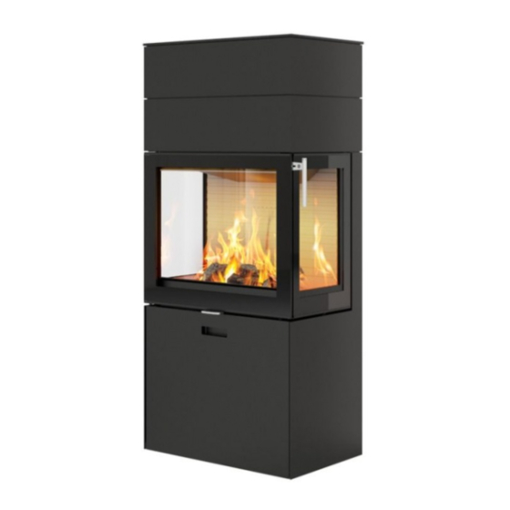
- Page 1 OSITIV 600 MAX 600 MAX/E UTLINE BRUGERVEJLEDNING BEDIENUNGSANLEITUNG USER MANUAL MANUEL D’UTILISATEUR BRUKERVEILEDNING EGATIV BRUKSANVISNING KÄYTTÖOHJE GEBRUIKERHANDLEIDING...
- Page 2 Project manager: Approved: D M Y 07-09-2020 INDUSTRIVEJ 20, 9900 FREDERIKSHAVN, DENMARK Corrections: Phone +45 98 47 90 33 - Fax +45 98 47 92 91 E-mail: info@rais.dk - Homepage: www.rais.dk 600MAX Heat storage Drawing name: Project: Established: Format: Revision: Drawing no.:...
-
Page 3: Table Of Contents
INSTALLATION MANUAL CONTENTS Installation manual In general Chimney Technical data Specifications Dimensional sketches Information plate Installation Delivery packaging Disposal of packaging Installation distances Height adjustment Fitting/changing the handle Removing the combustion chamber lining External air connection - Air-System Lubricating hinges Fitting the smoke outlet spigot Fitting the top box Fitting the top plate... -
Page 4: Installation Manual
INSTALLATION MANUAL stalled on a flammable floor, national local regulations must be complied with, Thank you for choosing your new RAIS or including for the size of the non-flamma- ATTIKA product! This installation manu- ble plate, which must cover the floor in... -
Page 5: Technical Data
TECHNICAL DATA The technical data given below includes specifications, dimensional drawings and the information plate. SPECIFICATIONS Danish Technological Institute ref.: 300-ELAB-2431-EN / 300-ELAB-2515-EN 600 MAX 600 MAX/E Nominal output (kW) Min./Max. Output (kW): 4–8* 4–10* Heating area (m 50–120 50–150 Fireplace insert width/depth/height 688 X 440 X 1305 688 X 440 X 1305... -
Page 6: Dimensional Sketches
DIMENSIONAL SKETCHES 1123 1306 1203... - Page 7 DIMENSIONAL SKETCHES 1123 1306 1203...
-
Page 8: Information Plate
F: Veuillez lire et observer les instructions du mode d'emploi. FR: BOIS Foyer à durèe de combustion limitèe, homologué pour cheminée à connexions multiples. Utiliser seulement les combustibles recommandés. Hergestellt für /Produced for: ATTIKA FEUER AG, Brunnmatt 16, CH-6330 Cham / RAIS A/S, Industrivej 20, DK-9900 Frederikshavn... - Page 9 F: Veuillez lire et observer les instructions du mode d'emploi. FR: BOIS Foyer à durèe de combustion limitèe, homologué pour cheminée à connexions multiples. Utiliser seulement les combustibles recommandés. Hergestellt für /Produced for: ATTIKA FEUER AG, Brunnmatt 16, CH-6330 Cham / RAIS A/S, Industrivej 20, DK-9900 Frederikshavn...
-
Page 10: Installation
INSTALLATION INSTALLATION The following section explains how to install the fireplace insert and includes information about the packaging, installation distances etc. DELIVERY PACKAGING Upon delivery, the stove is secured to a transport pallet using four transport safety fit- tings, one in each corner (A). The safety fittings are secured with screws, which must be unscrewed. -
Page 11: Installation Distances
INSTALLATION DISTANCES INSTALLATION DISTANCES. IMPORTANT: Please bear in mind that the installation distances on the following pages only apply to the wood-burning stove. The final choice of Chimney solution may have a larger safety distance to the flammable material. The Chimney solution must always be installed in accordance with current building regulations and in a manner that en- sures CE-marking compliance. - Page 12 INSTALLATION DISTANCES INSTALLATION DISTANCE TO FLAMMABLE MATERIAL: 600MAX & 600MAX/E Three-sided The installation distances applicable to the wood-burning stove are shown below. Bear in mind that the final choice of chimney may have a different safety distance. If the floor is flammable, we recommend placing the stove on a non-flammable surface. All dimensions are in mm.
- Page 13 INSTALLATION DISTANCES Flammable ceiling Safety distances to the flammable ceiling and floor are measured from above and below the door.
-
Page 14: Height Adjustment
HEIGHT ADJUSTMENT HEIGHT ADJUSTMENT The stove is equipped with four adjustment screws (1) under the stove. Use the adjustment screws to ensure the wood-burning stove stands level. -
Page 15: Fitting/Changing The Handle
FITTING THE HANDLE FITTING/CHANGING THE HANDLE The wood-burning stove comes with a tem- porary handle (1). To remove it, undo the screws (2). The new handle (3) can now be fitted to the stove using the screws (2). -
Page 16: Removing The Combustion Chamber Lining
REMOVING THE COMBUSTION CHAMBER LINING REMOVING THE COMBUSTION CHAMBER LINING The combustion chamber lining protects the body of the fireplace insert from the heat of the fire. The large differences in temperature can lead to cracks in the combustion chamber lining. This will not affect the functionality of the fireplace insert. -
Page 17: External Air Connection - Air-System
Air-System Fresh air supplied through the floor. 1) Spigot 2) Hose clamp 3) Flexible hose 4) M5 screw 5) 3 mm Unbrako key 6) Valve 7) Double-sided adhesive gasket Place the foam ring (8) over the hole in the floor and place the stove on the ring so that the hole in the base plate is within the diameter of the foam ring. - Page 18 Air-System Fresh air supplied through the wall 1) Spigot 2) Hose clamp 3) Flexible hose 4) M5 screws 5) 3 mm Unbrako key 6) Valve 7) Double-sided adhesive gasket 8) Cover Cover Remove the cover on the rear of the stove and secure the flexible hose (3) on the spigot (1) using the hose clamp (2).
-
Page 19: Lubricating Hinges
LUBRICATING THE HINGES LUBRICATING THE HINGES & LOCK The fireplace must be lubricated regularly using the four moving parts on the lock and hinges (see image). Use heat-resistant oil. -
Page 20: Fitting The Smoke Outlet Spigot
Smoke outlet spigot MOUNTING OF SMOKE OUTLET SPIGOT THE SMOKE OUTLET SPIGOT CAN BE TURNED TWO WAYS. YOU CAN CHOOSE EITHER WAY. Version A uses the three free holes: 1) Ø8 Slits 2) M6 Nuts 3) M6 Washers 4) M6X20mm cylinder screws Version B uses the three threaded holes: 5) M6 threaded holes 6) M6X20mm cylinder screws... -
Page 21: Fitting The Top Box
TOP BOX FITTING THE TOP BOX. To install the top box, place it on the stove and insert the four M5x20mm spacers – one in every corner. After positioning the top box, adjust the intermediary space to 5 mm, then tighten the top box with the four M5x10 cylinder screws. M5X20mm Spacers 2) M5X10mm cylinder screws... -
Page 22: Fitting The Top Plate
Top plate FITTING THE TOP PLATE. To install the top plate, place it in position and insert the four M5x8 spacers supplied – one in every corner. Once the top plate is lowered in place over the spacers, all four bushings below the top plate must fit over the spacers. -
Page 23: Test Certificate
Info@teknologisk.dk Prøvningsattest III rev 1 Uddrag af rapport nr. 300-ELAB-2431-EN og 300-ELAB-2431-NS Emne: Pejseindsatse; Rais 600 eller Rais 600 Classic som Right, Left, 3 Side modeller samt fritstående ovn 600 MAX som Right, Left, 3 Side modeller Rekvirent: Rais A/S Industrivej 20, DK –... - Page 24 Phone +45 72 20 10 00 Notificeret prøvningsorgan med ID-nr. 1235 Info@teknologisk.dk Prøvningsattest IV Uddrag af rapport nr. 300-ELAB-2515-EN Emne: Rais 600 MAX/E incl rudevarianter m 1, 2, 3 glas Rekvirent: Rais A/S Industrivej 19, 9900 Frederikshavn Procedure: Prøvning efter DS/EN13240/A2:2004 Prøvning efter NS3058-1 &...
-
Page 25: Assessment Of Performance (Aop)
[Test report(s) No(s).] 300-ELAB-2431-EN covering A.4.7 – Level or class of performance – Performance at nominal Rais 600 Inset appliance heat output including units, where relevant -Energy efficiency 76% -Emission of CO 0,09% -Emission of OGC 54 mgC/Nm3* -Emission of NOx 69 mg/Nm3* -Emission of dust 5 mg/Nm3* [Test report(s) No(s).]... - Page 26 POSITIV OUTLINE NEGATIV RAIS A/S ATTIKA FEUER AG Industrivej 20 Brunnmatt 16 DK-9900 Frederikshavn CH-6330 Cham Denmark Switzerland www.rais.dk www.attika.ch...
Need help?
Do you have a question about the attika 600 MAX-1 and is the answer not in the manual?
Questions and answers