
Related Manuals for PANCONTROL PAN Stromkreisfinder


Summary of Contents for PANCONTROL PAN Stromkreisfinder
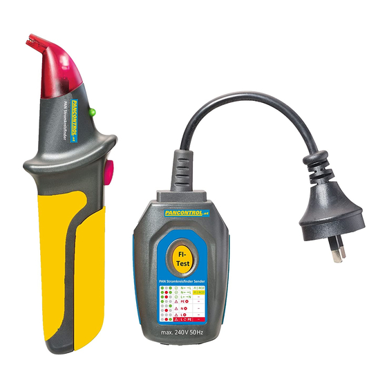
- Page 1 Receiver Transmitter/ GFCI Tester MANUAL PAN Stromkreisfinder Circuit Breaker Finder and GFCI/ Receptacle Tester ...
- Page 2 Congratulations on your purchase of the PAN Stromkreisfinder Circuit Breaker Finder and GFCI Receptacle Tester. For over 20 years the PANCONTROL brand is synonymous with practical, economical and professional measuring instruments. We are convinced that this device will serve you well for many years to ...
- Page 3 3. Safety This symbol adjacent to another symbol, terminal or operating device indicates that the operator must refer to an explanation in the Operating Instructions to avoid personal injury or damage to the meter. This symbol indicates that a device is protected throughout by double insulation or reinforced insulation. 4. Specifications Operating Voltage 200 to 240 V Operating Frequency 50 Hz ...
- Page 4 5. Operation WARNING: Always test on a known good circuit before use. Refer all indicated problems to a qualified electrician. Locating a Circuit Breaker or Fuse The transmitter injects a signal onto the circuit which can be detected by the receiver. The receiver will beep when the signal is detected. The scanning head is for tracing and pinpointing the exact circuit breaker or fuse protecting the selected circuit. Plug the Transmitter / Receptacle Tester into a powered outlet. If Hot is on the right, the two green LEDs illuminate. If Hot is on the left, one green and the red LED illuminate. The tester works in both cases. Press and release to ON/OFF button. The red LED 1 should turn on and the LED 2 should turn green. If the LED 2 should ...
- Page 5 Receptacle Wiring Test Plug the Transmitter / Receptacle tester into the outlet with the cable showing downwards and the GFCI test button showing upwards. The three LEDs will indicate circuit condition. The diagram lists all of the conditions that the tester can detect. Hot right, Neutral left Hot right, GFCI Test in Progress Hot left and Neutral open Hot and Ground reversed Hot left, Neutral right Open Hot Hot right and Neutral open Open Ground OFF ON Please note: The tester will not indicate the quality of the ground connection, 2 hot wires in a circuit, reversal of ground and neutral conductors or a combination of defects. ...
- Page 6 6. Replacing the Battery 1. When the LED 2 should turn red, the battery is low and should be replaced. 2. Remove slide off cover to replace batteries.(The Transmitter is line powered.) 3. Install 9 V battery observing the correct polarity. 4. Re‐install battery cover 5. Dispose of the old battery properly. Note: To maximize battery life an auto‐power off function is incorporated in the receiver which will turn the receiver off about 3 minutes of inactivity. To resume testing after this period just turn the unit on as described above. 7. Guarantee and spare parts ...
Need help?
Do you have a question about the PAN Stromkreisfinder and is the answer not in the manual?
Questions and answers