Table of Contents
Advertisement
Advertisement
Table of Contents

Subscribe to Our Youtube Channel
Related Manuals for Cooper & Hunter AIR-MASTER Series


Summary of Contents for Cooper & Hunter AIR-MASTER Series
- Page 1 SERVICE MANUAL Change for Life Split Air Conditioner AIR-MASTER Series M ODELS : CH-S 18RX4 CH-S 24RX4 For proper operation, please read and keep this manual carefully. Designed by Cooper&Hunter International Corporation, Oregon, USA www.cooperandhunter.com...
-
Page 2: Table Of Contents
Service Manual Table of Contents Part Ⅰ : Technical Information ...............1 1. Summary ........................1 2. Specifications ......................2 2.1 Specification Sheet ......................2 2.2 Capacity Curve in Different Outdoor Temperature ............6 2.3 Cooling and Heating Data Sheet in Rated Frequency .............6 3. - Page 3 Service Manual 10. Exploded View and Parts List ..............40 10.1 Indoor Unit ........................40 10.2 Outdoor Unit .........................42 11. Removal Procedure ..................46 11.1 Removal Procedure of Indoor Unit ................46 11.2 Removal Procedure of Outdoor Unit ................51 Appendix: .
-
Page 4: Part Ⅰ : Technical Information
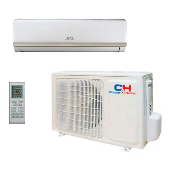
Service Manual Part Ⅰ : Technical Information 1. Summary Indoor Unit Outdoor Unit Remote ControlIer Technical Information... -
Page 5: Specifications
Service Manual 2. Specifications 2.1 Specification Sheet Model CH-S18RX4 Product Code CA428000302 Rated Voltage V ~ 220-240 Power Rated Frequency Supply Phases Power Supply Mode Indoor Cooling Capacity 4700 Heating Capacity 4900 Cooling Power Input 1460 Heating Power Input 1430 Cooling Power Current Heating Power Current Rated Input... - Page 6 Service Manual Model of Outdoor Unit CH-S18RX4 Outdoor Unit Product Code CA414W00102 Compressor Manufacturer/Trademark ZHUHAI LANDA COMPRESSOR CO.,LTD. Compressor Model QXA-C18B030G3 Compressor Oil RB68EP Compressor Type Rotary L.R.A. Compressor RLA Compressor Power Input 1520 Overload Protector UP3-A6C Throttling Method Capillary Operation Temp ºC 16~30...
- Page 7 Service Manual Model CH-S24RX4 Product Code CA428000403 Rated Voltage V ~ 220-240 Power Rated Frequency Supply Phases Power Supply Mode Indoor Cooling Capacity 6150 Heating Capacity 6500 Cooling Power Input 1900 Heating Power Input 1900 Cooling Power Current 8.64 Heating Power Current 8.64 Rated Input 2700...
- Page 8 Service Manual Model of Outdoor Unit CH-S24RX4 Outdoor Unit Product Code CA136W0043 Compressor Manufacturer/Trademark ZHUHAI LANDA COMPRESSOR CO.,LTD Compressor Model QXA-F232F050 Compressor Oil RB68EP Compressor Type Rotary L.R.A. Compressor RLA Compressor Power Input 1930 Overload Protector UP3-27 Throttling Method Capillary Operation Temp ºC 16~30...
-
Page 9: Capacity Curve In Different Outdoor Temperature
Service Manual 2.2 Capacity Curve in Different Outdoor Temperature Cooling: Heating: Condition Cooling Condition Heating Indoor:DB27°C WB19°C Indoor:DB20°C Indoor air flow: Super High Indoor air flow: Super High Pipe length:4m or 5m Pipe length:4m or 5m Outdoor t emp.(°C) Outdoor t emp.(°C) 2.3 Cooling and Heating Data Sheet in Rated Frequency Cooling Pressure of gas pipe... -
Page 10: Outline Dimension Diagram
Service Manual 3. Outline Dimension Diagram 3.1 Indoor Unit 2XΦ55 Unit: mm Technical Information... -
Page 11: Outdoor Unit
Service Manual 3.2 Outdoor Unit Unit: mm Unit: mm Technical Information... -
Page 12: Refrigerant System Diagram
side Valve Capillary Strainer Service Manual 4. Refrigerant System Diagram COOLING Cooling and heating model Outdoor unit Indoor unit Gas pipe side Valve 4-Way valve Di s charge Heat Suction Accumlator exchanger Compressor (evaporator) Heat exchanger Liquid pipe (condenser) side Valve Capillary Strainer... -
Page 13: Electrical Part
Service Manual 5. Electrical Part 5.1 Wiring Diagram ●Instruction Symbol Symbol Color Symbol Symbol Color Symbol Name White Green Jumper cap Yellow Brown COMP Compressor Blue Grounding wire YEGN Yellow/Green Black Violet Orange Note: Jumper cap is used to determine fan speed and the swing angle of horizontal lover for this model. ●... - Page 14 Service Manual BN(BK) RECEIVER AND BU(WH) DISPLAY BOARD YEGN(GN) ROOM TEMP. TUBE TEMP. SENSOR SENSOR DISPLAY POWER EARTH-PLATE YEGN YEGN EVAPORATOR L101 ROOM DISP1 TUBE DISP2 N(1) AP1 PRINTED CIRCUIT BOARD COMP L(AC-L) (SWING) SWING-UD PG PGF JUMP OFAN CONNECTING TERMINAL CABLE BLOCK...
- Page 15 Service Manual ● Outdoor Unit YEGN These wiring diagrams are subject to change without notice; please refer to the one supplied with the unit. Technical Information...
-
Page 16: Pcb Printed Diagram
Service Manual 5.2 PCB Printed Diagram ● Top view Name ● Bottom view Technical Information... -
Page 17: Function And Control
Service Manual 6. Function and Control 6.1 Remote Controller Introduction Buttons on Remote Controller Introduction for Icons on Display Screen Set fan speed Operation mode Send signal Auto mode X-fan mode Cool mode Dry mode Set temperature Fan mode Turbo mode Heat mode Set time TIMER ON /... - Page 18 Service Manual Press this button, the unit will be turned on, press it once more, the unit will be turned off. When turning on or turning off the unit, the Timer, Sleep function will be canceled, but the presetting time is still remained. 2.
- Page 19 Service Manual in AUTO, FAN or HEAT mode. 9. TEMP Button a. Press this button, could select displaying the indoor setting temperature or indoor ambient temperature. When the indoor unit firstly power on it will display the setting temperature, if the temperature's displaying status is changed from other status to " ", displays the ambient temperature, 5s later or within 5s, it receives other remote control signal that will return to display the setting temperature.
- Page 20 Service Manual 2. Press "MODE" button to select your required mode: AUTO, COOL, DRY, FAN,HEAT. 3. Press "+" or "-" button to set your required temperature. (Temperature can’t be adjusted under auto mode). 4. Press "FAN" button to set your required fan speed: auto, low, medium and high speed. 5.
-
Page 21: Brief Description Of Modes And Functions
Service Manual 6.2 Brief Description of Modes and Functions Display Receiver Operation icon Cooling icon window Dual-8 nixie Heating icon Drying icon tube display (Display content or position may be different from above graphics, please refer to actual products) Start cooling Tamb. - Page 22 Service Manual Freeze protection period 3 min Compressor Outdoor fan motor Indoor fan motor Set fan speed amb. Cooling preset Drying preset- Stop 6 min 6min. 4min. 4min. Compressor Outdoor fan motor Indoor fan motor Low speed Technical Information...
- Page 23 Service Manual Stop heating preset Original operating status preset Start heating min. Compressor Outdoor unit Intdoor unit Set fan speed min. Set fan speed min. Reversing valve Technical Information...
- Page 24 Service Manual Emergency Press OFF status ON status(Auto mode) operation switch Press O(0°) Technical Information...
- Page 25 Service Manual Overcurrent protection Zero-crossing inspection circuit malfunction of the IDU fan motor Technical Information...
-
Page 26: Part Ⅱ : Installation And Maintenance
Service Manual Part Ⅱ : Installation and Maintenance 7. Notes for Installation and Maintenance Safety Precautions: 10. If the power cord or connection wire is not long enough, please get the specialized power cord or connection wire Important! from the manufacture or distributor. Prohibit prolong the wire by yourself. - Page 27 Service Manual Main Tools for Installation and Maintenance 1. Level meter, measuring tape 2. Screw driver 3. Impact drill, drill head, electric drill 4. Electroprobe 5. Universal meter 6. Torque wrench, open-end wrench, inner hexagon spanner 7. Electronic leakage detector 8.
-
Page 28: Installation
Service Manual 8. Installation 8.1 Installation Dimension Diagram Space to the wall At least 15cm At least 15cm Space to the wall Drainage pipe Installation and Maintenance... - Page 29 Service Manual Installation procedures Start installation Preparation before installation Read the requirements select installation Prepare tools for electric connection location Select indoor unit Select outdoor unit installation location installation location Install the support of outdoor unit Install wall-mounting (select it according to the actual situation) frame, drill wall holes Connect pipes of indoor Fix outdoor unit...
-
Page 30: Installation Parts-Checking
Service Manual 8.2 Installation Parts-checking 8.4 Electric Connection Requirement Name Name 1. Safety Precaution Indoor unit Sealing gum (1) Must follow the electric safety regulations when installing Outdoor unit Wrapping tape the unit. Support of outdoor (2) According to the local safety regulations, use qualified Connection pipe unit power supply circuit and air switch. - Page 31 Service Manual (3) Fix the wall-mounting frame on the wall with tapping screws 5. Connect the Pipe of Indoor Unit (ST4.2X25TA) and then check if the frame is firmly installed by (1) Aim the pipe joint at the corresponding bellmouth.(As show pulling the frame.
- Page 32 Service Manual 7. Connect Wire of Indoor Unit 8. Bind up Pipe (1) Open the panel, remove the screw on the wiring cover and (1) Bind up the connection pipe, power cord and drain hose then take down the cover.(As show in Fig.11) with the band.(As show in Fig.14) (2) Reserve a certain length of drain hose and power cord for installation when binding them.
-
Page 33: Installation Of Outdoor Unit
Service Manual 8.6 Installation of Outdoor Unit Refer to the following table for wrench moment of force: Tightening torque(N . m) 1. Fix the Support of Outdoor Unit(Select it according to Hex nut diameter(mm) the actual installation situation) Φ6 15~20 Φ9.52 30~40 (1) Select installation location according to the house structure. -
Page 34: Vacuum Pumping And Leak Detection
Service Manual (3) The water outlet cant be placed in water in order to drain 8.8 Check after Installation and Test smoothly.(As show in Fig.27) Operation 1. Check after Installation Check according to the following requirement after finishing installation. The drain hose can't be fluctuant Items to be checked Possible malfunction Has the unit been... -
Page 35: Maintenance
Service Manual 9. Maintenance 9.1 Error Code Display Method of Indoor Unit Indicator lamp (Only for the unit with indictor; Possible Causes(For specific maintenance Malfunction Error during blinking, ON for A/C Status method, please refer to the following procedure of Name troubleshooting) Code... -
Page 36: Procedure Of Troubleshooting
Service Manual 9.2 Procedure of Troubleshooting 1. Malfunction of Temperature Sensor F1, F2 Troubleshooting for F1,F2 malfunction the wiring terminal between the temperature sensor and the controller loosened or poorly contacted? Insert the temperature sensor tightly Is malfunction eliminated Is there short circuit due to trip - over of the parts? Make the parts upright Is malfunction... - Page 37 Service Manual 2. Malfunction of Blocked Protection of IDU Fan Motor H6 Troubleshooting for H6 malfunction Stir the blade with a tool to see whether the blade rotates smoothly Tighten the screw; reassemble the blade, motor and shaft bearing rubber base sub-assy to make sure there is no foreign object between them Is malfunction eliminated...
- Page 38 Service Manual 3. Malfunction of Protection of Jumper Cap C5 Troubleshooting for C5 malfunction Appearance of Is there jumper cap on the the jumper cap mainboard ? Assemble the jumper cap with the same model Is malfunction eliminated the jumper cap inserted correctly and tightly ? Insert the...
- Page 39 Service Manual 4. Malfunction of Overcurrent Protection E5 Troubleshooting for E5 malfunction Is the supply voltage unstable Normal fluctuation is within 10 % of the rated Malfunction is with big fluctuation? voltage on the nameplate eliminated Is the supply voltage too low Malfunction is Adjust the supply voltage to maintain it within Malfunction is...
- Page 40 Service Manual 5. Malfunction of Zero-crossing Inspection Circuit Malfunction of the IDU Fan Motor U8 Troubleshooting for U8 malfunction Re-energize1 minute after de-erergization The unit returns to normal. Conclusion:U8 is displayed due U8 is still to instant energization afte de- displayed energization while the capacitor discharges slowly.
-
Page 41: Maintenance Method For Normal Malfunction
Service Manual 9.3 Maintenance Method for Normal Malfunction 1. Air Conditioner Can't be Started Up Possible Causes Discriminating Method (Air conditioner Status) Troubleshooting Confirm whether it's due to power failure. If yes, No power supply, or poor After energization, operation indicator isn’t bright wait for power recovery. - Page 42 Service Manual 4. ODU Fan Motor Can't Operate Possible causes Discriminating method (air conditioner status) Troubleshooting Connect wires according to wiring diagram to Wrong wire connection, or poor Check the wiring status according to circuit make sure all wiring terminals are connected connection diagram firmly...
-
Page 43: Exploded View And Parts List
Service Manual 10. Exploded View and Parts List 10.1 Indoor Unit Installation and Maintenance... - Page 44 Service Manual Part Code Description CH-S18RX4 CH-S24RX4 Product code CA428N00302 CA428N00403 Front Panel Assy 20022512 20022512 Display Board 30565110 30565110 Filter Sub-Assy 1112208901 1112208901 Screw Cover 242520179 242520179 Front Case Sub-assy 2001266701 2001266701 Rear Case assy 22202193 22202193 Guide Louver 1051220501 1051220501 Air Louver 1...
-
Page 45: Outdoor Unit
Service Manual 10.2 Outdoor Unit Installation and Maintenance... - Page 46 Service Manual Part Code Description CH-S18RX4 Product code CA414W00102 Front Grill 22413433 Front Panel 0153303204P Chassis Sub-assy 0120324510 Drainage Connecter 06123401 Magnet Coil 43000400 Compressor and Fittings 00103891 4-Way Valve 430004032 4-Way Valve Assy 03123986 StrainerA 07210022 Capillary Sub-assy 03163101 Right Side Plate Assy 0130200404 Valve...
- Page 47 Service Manual Installation and Maintenance...
- Page 48 Service Manual Part Code Description No.. CH-S24RX4 Product code CA136W0043 Front grill 22415001 Left Handle Front Panel 01435001 Axial Flow Fan 10335257 Fan Motor 15015057 Motor Support Sub-Assy 0170305901 Top Cover 01255001 Clapboard Sub-Assy 01233035 Electric Box Assy 02613155 Condenser Assy 01163524 Rear Grill 01473069...
-
Page 49: Removal Procedure
Service Manual 11. Removal Procedure Caution: discharge the refrigerant completely before removal. 11.1 Removal Procedure of Indoor Unit Steps Procedure 1.Before disassembly Open the front panel . to remove it. Filter Remove axial sleeve of horizontal louver and bend the louver slightly. Then remove the louver. - Page 50 Service Manual Indicator 3.Removal of indicator and front panel Remove connection screw of indicator and then remove the indicator. Screw Front Panel Assy Remove rotating shaft of front panel and then remove the front panel. 4.Removal of electric box cover 2 Screw Remove connection screws between electric box cover 2 and front case.
- Page 51 Service Manual 5. Removal of front case Remove connection screws between front case and rear case. Screw Clasp Release clasp connecting front case and rear case and then remove the front case. 6. Removal of vertical louver Remove 10 clasps of vertical louver and rear case assy.
- Page 52 Service Manual 7. Removal of electric box assy Indoor Temp Sensor Unplug indoor temp sensor. Electric Box Cover Remove connection screws of electric box assy and rear case. Release clasps and remove connection screws of earthing wire and evaporator assy. Then remove electric Electric Box Assy box assy.
- Page 53 Service Manual 9.Removal of cross flow fan and motor Remove screws of step motor and then remove the motor. Step Motor Remove 4 connection screws of motor clamp and rear case. Then remove motor clamp. Motor Press Plat Remove cross flow fan and motor. O-Gasket Sub-assy of Bearing Removal of ring of bearing sub-assy.
-
Page 54: Removal Procedure Of Outdoor Unit
Service Manual 11.2 Removal Procedure of Outdoor Unit Steps 1. Before disassembly 2. Remove big handle Remove the connection screw fixing the big big handle handle and then remove the handle. 3. Remove top cover plate top panel Remove connection screws connecting the top panel with the front panel and the right side plate, and then remove the top panel. - Page 55 Service Manual Steps 4. Remove front grille Remove connection screws between the front grille and the front panel. Then remove the front grille. front grille 5. Remove front panel Remove connection screws connecting the front panel with the chassis and the motor support and then remove the front panel.
- Page 56 Service Manual Steps 7. Remove axial flow blade axial flow blade Remove the nut on the blade and then remove the axial flow blade. 8. Remove motor and motor support Remove the 4 tapping screws fixing the motor and motor support disconnect the leading wire insert of the motor.
- Page 57 Service Manual Steps 10. Remove isolation sheet isolation sheet Remove the 3 screws fixing the isolation sheet and then remove the isolation sheet. 11. Remove soundproof sponge Remove the soundproof sponge wrapping the compressor. soundproof sponge 12. Remove magnet coil Remove the screw fixing the magnet coil and then remove the coil.
- Page 58 Service Manual 13. Remove liquid valve and gas valve Unsolder the welding joint connecting the capillary, valves and the outlet pipe of condenser to remove the capillary. Do not block the capillary with welding slag during unsoldering. Remove the 2 screws fixing the gas valve and unsolder the welding joint between the gas valve liquid valve and the air-return pipe to remove the gas valve.
- Page 59 Service Manual Steps Procedure 1. Before disassembly 2. Remove handle handle Remove the screw fixing the handle and then remove the handle. screw 3. Remove top panel and grille top panel Remove screws fixing the top panel and the grille respectively, and then remove the top panel and the grille.
- Page 60 Service Manual Steps Procedure 4. Remove front panel and rear guard grille rear guard grille screw panel Remove screws fixing the front panel and the rear guard grille respectively, and then remove the front panel and the rear guard grille. screw screw 5.
- Page 61 Service Manual Steps Procedure 7. Remove motor and motor support motor support Remove screws on the motor and the motor motor support, and then remove the motor and the motor support. screw 8. Remove electric box electric box assy Remove the 2 screws fixing the electric box; loosen the wire bundle;...
- Page 62 Service Manual Steps Procedure 10. Remove solenoid coil Remove the screw on the solenoid coil, and then remove the solenoid coil. solenoid coil screw 11. Remove compressor 4-way valve assy compressor Unsolder the pipes (including the soldering joint among the 4-way valve, the compressor, the condenser, the gas valve and the liquid valve) connected to the compressor at first.
- Page 63 Service Manual Steps Procedure 12. Remove isolation sheet Remove the 3 screws fixing the isolation sheet and then remove the isolation sheet. isolation sheet screw 13. Remove valve support and condenser Remove screws fixing the valve support condenser and then remove the valve support; Remove the screw fixing the condenser and then pull the condenser upwards to remove it.
-
Page 64: Appendix
Service Manual Appendix: Appendix 1: Reference Sheet of Celsius and Fahrenheit Conversion formula for Fahrenheit degree and Celsius degree: Tf=Tcx1.8+32 Set temperature Fahrenheit Fahrenheit Fahrenheit display Fahrenheit display Fahrenheit display Fahrenheit Celsius (℃) Celsius (℃) Celsius (℃) temperature temperature temperature (℉)... -
Page 65: Appendix 3: Pipe Expanding Method
Service Manual Appendix 3: Pipe Expanding Method Pipe Note: Pipe cutter Improper pipe expanding is the main cause of refrigerant leakage.Please expand the pipe according to the following steps: A:Cut the pip Leaning Uneven Burr ● Confirm the pipe length according to the distance of indoor unit and outdoor unit. ●... -
Page 66: Appendix 4: List Of Resistance For Temperature Sensor
Service Manual Appendix 4: List of Resistance for Temperature Sensor Resistance Table of Ambient Temperature Sensor for Indoor and Outdoor Units(15K) Temp( C) Resistance(kΩ) Temp( C) Resistance(kΩ) Temp( Resistance(kΩ) Temp( Resistance(kΩ) 138.1 18.75 3.848 1.071 128.6 17.93 3.711 1.039 121.6 17.14 3.579 1.009... - Page 67 Service Manual Resistance Table of Tube Temperature Sensors for Indoor and Outdoor (20K) Temp( C) Resistance(kΩ) Temp( C) Resistance(kΩ) Temp( Resistance(kΩ) Temp( Resistance(kΩ) 181.4 25.01 5.13 1.427 171.4 23.9 4.948 1.386 162.1 22.85 4.773 1.346 153.3 21.85 4.605 1.307 20.9 4.443 1.269 137.2...
- Page 68 Service Manual Resistance Table of Discharge Temperature Sensor for Outdoor(50K) Temp( C) Resistance(kΩ) Temp( Resistance(kΩ) Temp( C) Resistance(kΩ) Temp( Resistance(kΩ) 853.5 18.34 4.75 799.8 93.42 17.65 4.61 89.07 16.99 4.47 703.8 84.95 16.36 4.33 660.8 81.05 15.75 4.20 620.8 77.35 15.17 4.08 580.6...
- Page 69 Designed by Cooper&Hunter International Corporation, Oregon, USA www.cooperandhunter.com E-mail: info@cooperandhunter.com...
Need help?
Do you have a question about the AIR-MASTER Series and is the answer not in the manual?
Questions and answers