Table of Contents
Advertisement
Available languages
Available languages
Advertisement
Table of Contents

Related Manuals for Cooper & Hunter Arctic Series


Summary of Contents for Cooper & Hunter Arctic Series
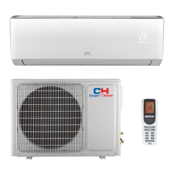
- Page 1 OWNER’S MANUAL Heat Pump Air To Air Arctic Series M ODELS : CH-S09FTXLA CH-S12FTXLA CH-S18FTXLA CH-S24FTXLA For proper operation, please read and keep this manual carefully. Designed by Cooper&Hunter International Corporation, Oregon, USA www.cooperandhunter.com...
-
Page 2: Table Of Contents
Content Operation Notices Precautions......................1 Parts Name......................6 ScreenOperation Guide Buttons on remote controller ................8 Introduction for icons on display screen .............. Introduction for buttons on remote controller ............9 Replacement of batteries in remote controller ...........12 Emergency operation . -
Page 3: Precautions
Precautions WARNING Operation and Maintenance This appliance can be used by children aged from 8 years and above and persons with reduced physical, sensory or mental capabilities or lack of experience and knowledge if they have been given supervision or instruction concerning use of the appliance in a safe way and understand the hazards involved. - Page 4 Precautions WARNING Maintenance must be performed by qualified professionals. Otherwise, it may cause personal injury or damage. Do not repair heat pump by yourself. It may cause electric shock or damage. Please contact dealer when you need to repair heat pump. Do not extend fingers or objects into air inlet or air outlet.
- Page 5 Precautions WARNING Attachment Installation must be performed by qualified professionals. Otherwise, it may cause personal injury or damage. Must follow the electric safety regulations when installing the unit. According to the local safety regulations, use qualified power supply circuit and circuit break. Do install the circuit break.
- Page 6 Precautions WARNING Do not put through the power before finishing installation. If the supply cord is damaged, it must be replaced by the manufacturer, its service agent or similarly qualified persons in order to avoid a hazard. The temperature of refrigerant circuit will be high, please keep the interconnection cable away from the copper tube.
- Page 7 Precautions WARNING For the heat pump with plug ,the plug should be reachable after finishing installation. For the heat pump without plug, an circuit break must be installed in the line. If you need to relocate the heat pump to another place, only the qualified person can perform the work.
-
Page 8: Parts Name
Parts Name Indoor Unit air inlet panel aux.button horizontal louver cooling power receiver air outlet indicator indicator window display heating temp. drying indicator indicator indicator (Display content or position may be different from above graphics, please refer to actual products) NOTICE: Actual product may be different from above graphics, please refer to actual products. - Page 9 Parts Name Display For some model: For some model: temp. cooling power receiver indicator indicator indicator window heating indicator display cooling indicator receiver power heating temp. drying window indicator display indicator indicator indicator drying indicator For some model: display temp. indicator Power LED color indicator: Green-status-ON.
-
Page 10: Buttons On Remote Controller
Buttons on remote controller ON/OFF Press it to start or stop operation. : Press it to decrease temperature setting. : Press it to increase temperature setting. MODE Press it to select operation mode (AUTO/COOL/DRY/FAN/HEAT). Press it to set fan speed. SWING Press it set swing angle. -
Page 11: Introduction For Buttons On Remote Controller
Introduction for buttons on remote controller ON/OFF : Press this button to turn on the unit .Press this button again to turn off the unit. Press this button to decrease set temperature. Holding it down above 2 seconds rapidly decreases set temperature. In AUTO mode, set temperature is not adjustable. Press this button to increase set temperature.Holding it down above 2 seconds rapidly increases set temperature. - Page 12 Introduction for buttons on remote controller ress this button to achieve the on and off of healthy and scavenging functions in operation status.Press this button for the first time to start scavenging function; LCD displays“ ”. Press the button for the second time to start healthy and scavenging functions simultaneously;...
- Page 13 Introduction for buttons on remote controller TEMP: Press this button, could select displaying the indoor setting temperature or indoor ambient temperature.When the indoor unit firstly power on it will display the setting temperature, if the temperature's displaying status is changed from other status to" ",displays the ambient temperature, 3s later or within 3s, it receives other remote control signal that will return to display the setting temperature.
-
Page 14: Replacement Of Batteries In Remote Controller
Introduction for buttons on remote controller Combination of "+" and "-" buttons: About lock Press "+ " and "-" buttons simultaneously to lock or unlock the keypad. If the remote controller is locked, is displayed. In this case, pressing any button, blinks three times. -
Page 15: Emergency Operation
Emergency operation If remote controller is lost or damaged, please use auxiliary button to turn on or turn off the heat pump. The operation in details are as below: heat pump. When the heat pump is turned on, it will operate under auto mode. -
Page 16: Clean And Maintenance
Clean and Maintenance Clean filter Clean filter Open panel Pull out the panel to a certain ● Use dust catcher or water to angle as shown in the fig. clean the filter. ● When the filter is very dirty, use the water (below 45℃... - Page 17 Clean and Maintenance NOTICE: Checking before use-season 1. Check whether air inlets are blocked. 2. Check whether air switch,plug and socket are in good condition. 3. Check whether filter is clean. 4. Check whether drainage pipe is damaged. NOTICE: Checking after use-season 1.
-
Page 18: Malfunction Analysis
Malfunction analysis General phenomenon analysis Please check below items before asking for maintenance. If the malfunction still can’t be eliminated, please contact local dealer or qualified professionals. Phenomenon Check items Solution ● Whether it's interfered severely ● Pull out the plug. Reinsert (such as static electricity,stable the plug after about 3min, and voltage)? - Page 19 Malfunction analysis Phenomenon Check items Solution ● Power failure? ● Wait until power recovery. ● Is plug loose? ● Reinsert the plug. ● Air switch trips off or fuse is ● Ask professional to replace burnt out? air switch or fuse. Heat pump ●...
- Page 20 Malfunction analysis Phenomenon Check items Solution ● Whether there’s odour source, ● Eliminate the odour source. Odours are such as furniture and cigarette, emitted ● Clean the filter. etc. Heat pump ● Whether there’s interference, ● Disconnect power, put back operates such as thunder, wireless power, and then turn on the...
- Page 21 Malfunction analysis Error Code ● When heat pump status is abnormal, temperature indicator on indoor unit will blink to display corresponding error code. Please refer to below list for identific- ation of error code. Error code Troubleshooting It can be eliminated after restarting the unit. If not , please It can be eliminated after restarting the unit.
-
Page 22: Installation Dimension Diagram
Installation dimension diagram Space to the wall At least 15cm At least 15cm Space to the wall... -
Page 23: Tools For Installation
Tools for installation 1 Level meter 2 Screw driver 3 Impact drill 4 Drill head 5 Pipe expander 6 Torque wrench 7 Open-end wrench 8 Pipe cutter 9 Leakage detector 10 Vacuum pump 11 Pressure meter 12 Universal meter 13 Inner hexagon spanner 14 Measuring tape Note: ●... -
Page 24: Requirements For Electric Connection
Requirements for electric connection Safety precaution 1. Must follow the electric safety regulations when installing the unit. 2. According to the local safety regulations, use qualified power supply circuit and air switch. 3. Make sure the power supply matches with the requirement of heat pump. Unstable power supply or incorrect wiring or malfunction. -
Page 25: Installation Of Indoor Unit
Installation of indoor unit Step one: choosing installation location rm it with the client. Step two: install wall-mounting frame 1. Hang the wall-mounting frame on the wall; adjust it in horizontal position with the plastic expansion particles in the holes. 3. - Page 26 Installation of indoor unit Indoor outdoor Note: ● Pay attention to dust prevention and take relevant safety measures when opening the hole. Φ55/ 5-10 Φ70 ● The plastic expansion particles are not provided and should be bought locally. Step four: outlet pipe 1.
- Page 27 Installation of indoor unit Hex nut diameter Tightening torque (N . m) open-end wrench Φ 6 15~20 Φ 9.52 30~40 union nut Φ 12 45~55 pipe Φ 16 60~65 torque wrench Φ 19 70~75 indoor pipe 4. Wrap the indoor pipe and joint of con- nection pipe with insulating pipe, and then wrap it with tape.
- Page 28 Installation of indoor unit 2. Make the power connection wire go cable-cross through the cable-cross hole at the back hole of indoor unit and then pull it out from the front side. power connection wire 3. Remove the wire clip; connect the power connection wire to the wiring terminal according to the color;...
- Page 29 Installation of indoor unit Step eight: bind up pipe 1. Bind up the connection pipe, power drain hose connection pipe band cord and drain hose with the band. indoor and outdoor power cord indoor unit pipe indoor power cord liquid pipe 3.
-
Page 37: Check After Installation
Check after installation ● Check according to the following requirement after finishing installation. Items to be checked Possible malfunction Has the unit been installed firmly? The unit may drop, shake or emit noise. Have you done the refrigerant leakage It may cause insufficient cooling test? (heating) capacity. - Page 38 Configuration of connection pipe 1. Standard length of connection pipe ● 5m, 7.5m, 8m. 2.Min. length of connection pipe is 3m. 3.Max. length of connection pipe and max. high difference. Max length Max length Cooling Max height Cooling Max height of connec- of connec- capacity...
- Page 39 Configuration of connection pipe Additional refrigerant charging amount for R22, R407C, R410A and R134a Diameter of connection pipe Outdoor unit throttle Liquid pipe(mm) Gas pipe(mm) Cooling only(g/m) Cooling and heating(g/m) Φ6 Φ9.52 or Φ12 Φ6 or Φ9.52 Φ16 or Φ19 Φ12 Φ19 or Φ22.2 Φ16...
-
Page 40: Pipe Expanding Method
Pipe expanding method Note: Improper pipe expanding is the main cause of refrigerant leakage. Please expand the pipe according to the following steps: A: Cut the pipe E: Expand the port ● Confirm the pipe length according to ● Expand the port with expander. the distance of indoor unit and hard outdoor unit. - Page 41 Designed by Cooper&Hunter International Corporation, Oregon, USA www.cooperandhunter.com E-mail: info@cooperandhunter.com 66160000078...
- Page 42 РУКОВОДСТВО ПО ЭКСПЛУАТАЦИИ Бытовой Тепловой Насос Серия Arctic МОДЕЛИ: CH-S09FTXLA CH-S12FTXLA CH-S18FTXLA CH-S24FTXLA Пожалуйста, внимательно изучите данное руководство перед началом работы Designed by Cooper&Hunter International Corporation, Oregon, USA www.cooperandhunter.com...
- Page 43 Меры предосторожности Пожалуйста, прочитайте следующее прежде, чем использовать оборудование! ПРЕДУПРЕЖДЕНИЕ ★ ★ ★ При появлении запаха Не касайтесь Предохраняйте от дыма немедленно обес- оборудования повреждений точьте и мокрыми руками электрический кабель и свяжитесь с сервисным кабель межблочной центром связи. Если изоляция кабеля...
- Page 44 Меры предосторожности ★ Убедитесь, Для собственной ★ Устанавливайте ★ что оборудование безопасности отключайте наиболее подходящую надежно заземлено от температуру источника питания перед обслуживанием, ремонтом и чисткой, а также если планируете не Установить темп. использовать его в помещении на 5 °С ниже, чем на длительное...
- Page 45 Меры предосторожности ★ ★ Не используйте кабель со скрутками Для изменения направления и поврежденный кабель. Если кабель горизонтального воздушного потока поврежден, пожалуйста, свяжитесь с используйте пульт дистанционного сервисным центром для его замены управления Вертикальные Горизонтальные жалюзи жалюзи ★ ★ ★ Не...
- Page 46 Название частей Внутренний блок Вход воздуха ⑴ ⑶ ⑺ ⑺ ⑹ Выход воздуха ⑷ ⑸ Обозначения на дисплее H O U R ONOFF ON OF F ⑵ :Охлаждение MOD E SW I NG I FEE L :Осушение SLEE P TE M P TI MER - ON CLOCK T IMER...
- Page 47 Пульт управления ON/OFF(вкл/выкл) Нажмите для запуска и остановки работы Нажмите для понижения температуры Нажмите для повышения температуры MODE (режим) Нажмите для выбора режима работы (AUTO/COOL/DRY/FAN/HEAT) FAN(вентилятор) Нажмите для изменения скорости вращения вентилятора SWING(жалюзи) Нажмите для изменения угла направления воздушного потока I FEEL (см.
- Page 48 Пульт управления Присутствует не во всех моделях SWING SLEEP Появляется при нажатии кнопки SWING. Отображает, что режим SLEEP активен. Нажмите еще раз, если хотите его выключить. Появляется при одновременном нажатии LIGHT кнопок «+» и «-». Нажмите их еще раз, чтобы снять Появляется...
- Page 49 Пульт управления FAN SPEED Появляется при нажатии кнопки Каждое нажатие кнопки FAN и активации режима. изменяет скорость вращения вентилятора AUTO-LOW-MED-HIGH X-FAN (Автоматическая – Низкая – – Средняя – Высокая). Появляется при нажатии кнопки X-FAN и активации режима. I FEEL Для отключения нажмите кнопку еще раз. Появляется...
- Page 50 Пульт управления Описание пульта управления Нажмите кнопку для включения или выключения теплового насоса. ON/OFF При включении теплового насоса наЖК-дисплее внутреннего блока знак индикации « » горит зеленым цветом. Нажмите кнопку для понижения желаемой температуры в помещении. Удерживание кнопки,нажатой в течение 2 секунд, быстро понизит значение устанавливаемой...
- Page 51 Пульт управления Описание пульта управления Нажмите кнопку для активации режима . ункци в При нажатии на кнопку в первый раз функция Если нажать второй раз, то оба режима: и нажатие функцию SLEEP Функция «SLEEP» («СОН») включается для отдыха или сна. Функция...
- Page 52 Пульт управления TEMP Нажмите кнопку TEMP. При каждом последующем нажатии на дисплее отображается: установленная температура , температура в помещении и температура на улице В процессе переключения между температурными датчиками с помощью кнопки TEMP заданная температура отображается всегда. Примечание: Температура на улице показывается не у всех моделей CLOCK Нажмите...
- Page 53 Пульт управления Комбинация «+» и «-» Одновременное нажатие кнопок «+» и «–» блокируют кнопки пульта управления. На дисплее появляется значок . Повторное нажатие снимает блокировку. Комбинация MODE и «-» Одновременное нажатие кнопок MODE и «–» переключает единицы измерения температуры между градусами Цельсия и Фаренгейта. Комбинация...
- Page 54 Аварийное включение Аварийное включение Если пульт дистанционного управления потерян или поврежден, вы можете воспользоваться кнопкой включения/выключения т расположенной на внутреннем блоке под лицевой панелью. После включения т будет работать в режиме AUTO и менять скорость вращения вентилятора автоматически. Алгоритм работы т - Кнопка...
- Page 55 Очистка и уход за оборудованием Внимание Отключите электропитание перед обслуживанием и ремонтом. Не брызгайте водой на блок для чистки из-за вероятности короткого замыкания. Протирайте блок сухой тряпкой или слегка влажной тряпкой, смоченной водой или легким раствором неагрессивного моющего средства. Не используйте растворители и абразивные моющие средства. Чистка...
- Page 56 Очистка и уход за оборудованием Проверьте перед использованием ① Убедитесь, что ничего не мешает забору и подаче воздуха. ② Проверьте батарейки пульта управления. ③ Проверьте крепежные кронштейны наружного блока на отсутствие повреждений. перед использованием ① Отключите электропитание. ② Очистите фильтры и корпус наружного и внутреннего блоков. ③...
- Page 57 Проблемы и их решения Внимание! Не ремонтируйте т самостоятельно. Для обслуживания и ремонта т обращайтесь в специализированные сервисные центры. Неправильный ремонт или обслуживание могут привести к короткому замыканию, пожару или поражению электрическим током. Пожалуйста, перед обращением в сервисный центр проверьте нижеприведенные моменты.
- Page 58 Проблемы и их решения Явление Неисправность Блок не включается. Есть ли электропитание? Вставлена ли вилка в розетку? Не отключен ли автомат токовой защиты? Возможно, напряжение электропитания слишком низкое или высокое (это должны проверить специалисты). Проверьте, может быть, выставлена работа выключен автомат по...
- Page 59 Проблемы и их решения Я в л е н и е Н е и п с р а в н о с ь т Нет подачи воздуха из внутреннего блока. В режиме обогрева, если температура теплообменника внутреннего блока слишком низкая, вентилятор не подает воздух в помещение, чтобы...
- Page 60 Советы по эксплуатации Охлаждение Описание Т забирает тепло в помещении и отводит через наружный блок, таким образом понижая температуру в помещении. Текущая холодопроизводительность зависит от температуры наружного воздуха. Защита от обмерзания Если т работает в режиме охлаждения при низкой температуре окружающего воздуха, теплообменник...
- Page 61 Советы по эксплуатации Диапазон работы оборудования В помещении, DB/WB °C На улице, DB/WB °C Макс. при охлаждении 32/23 48/26 Мин. при охлаждении 21/15 21/- Макс. при обогреве 27/- 24/18 Мин. при обогреве 20/- -25/- Оборудование может работать в режиме охлаждения при наружной температуре в диапазоне...
- Page 62 Прочтите перед установкой Внимание! 1. Оборудование должно устанавливаться специалистами, имеющими соответствующие лицензии и сертификаты, строго соблюдая все требования и нормы безопасности, а также требования данной инструкции. 2. Перед установкой обратитесь в местное представительство торговой марки или авторизованную компанию-установщик. Если оборудование было установлено неавторизованной компанией, то ошибки...
- Page 63 Прочтите перед установкой Выбор места установки внутреннего блока 1. Убедитесь, что ничего не препятствует входящим и исходящим потокам воздуха т 2. Выберите место, где сконденсированная вода будет отводиться беспрепятственно и легко. выполнить соединения с наружным блоком. 3. Выберите место, недоступное детям. 4.
- Page 64 Прочтите перед установкой Модель Автомат токовой защиты 10 A 16 A 25 A Примечание: 1. Убедитесь в надежности подключения кабеля питания и заземления. убедитесь, что выполненное подключение соответствует электросхеме. 2. Ошибка в подключении может привести к короткому замыканию или пожару. Требования...
- Page 65 Схема установки Схема установки Расстояние до потолка Более 15 см Расстояние до стены Более 15 см Более 15 см Расстояние до стены Сторона выхода воздуха Расстояние до пола Расстояния необходимые для правильного выбора места установки оборудования, включающие минимальные расстояния до препятствий Расстояние...
- Page 66 Установка внутреннего блока Установка монтажной пластины 1. Монтажная пластина должна быть установлена строго горизонтально. Это важно, т.к. в конструкции блока предусмотрен наклон ванночки нормального отвода конденсата. Если блок не установлен горизонтально, конденсат может не отводиться правильно. 2. Закрепите монтажную пластину на стене при помощи винтов и дюбелей. 3.
- Page 67 Проверка после установки перед первым пуском Проверка после установки Что проверить Возможные неисправности Блок может упасть, издавать шум или Блок надежно установлен? вибрацию Снижается эффективность работы Отсутствуют утечки хладагента? Конденсат может протекать Надежна теплоизоляция? Конденсат отводится нормально? Возможны протечки Электропитание соответствует Возможен...
- Page 68 Установка и обслуживание дополнительного фильтра Установка опционального фильтра Одновременно с двух сторон подденьте пальцами и откройте лицевую панель. Затем вытащите воздушные фильтры как показано на рис. а Рис. a Рис. б Вставьте опциональный фильтр в Фильр специальные пазы на воздушном фильтре как...
- Page 69 Designed by Cooper&Hunter International Corporation, Oregon, USA www.cooperandhunter.com E-mail: info@cooperandhunter.com 66160000078...
Need help?
Do you have a question about the Arctic Series and is the answer not in the manual?
Questions and answers