
Subscribe to Our Youtube Channel
Related Manuals for Cooper & Hunter CH-FW K2A Series


Summary of Contents for Cooper & Hunter CH-FW K2A Series
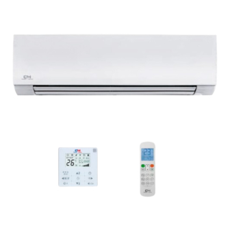
- Page 1 FCU Fancoils Service manual CH-FW**K2A Thank you for choosing commercial air conditioners. Please read this Owner’s Manual carefully before operation and retain it for future reference.
-
Page 2: Table Of Contents
50Hz Wall Mounted FCU Contents 1. Introduction ................. 2 2. Nomenclature ..............2 3. Product Schedule ............... 3 4. External Appearance ............3 5. Features ................4 6. Specifications ..............5 7. Dimension ................7 8. -
Page 3: Introduction
50Hz Wall Mounted FCU 1. Introduction Fan coil unit is a kind of compound device which assemble fan and heat-exchang coil together. Fan coil with fresh air supply system is a main type of center air-conditioner system, so it is an important component of AC devices. -
Page 4: Product Schedule
50Hz Wall l Mounted FCU 3. Product Schedule Air volume Type Power su upply (CFM) CH-FW025K2A CH-FW030K2A ll mounted 220~240V-1P Ph-50Hz CH-FW040K2A CH-FW 050K2A CH-FW060K2A 4. External l Appearan Product Sched dule... -
Page 5: Features
0Hz Wall Mou unted FCU 5. Features New pan nel supplies more choice e for custom Multi-con nnection out tlet pipe met thod: left/rig ht/rear, mor re flexible fo r installation Left pipin Left back pipi Right piping Right back p piping... -
Page 6: Specifications
50Hz Wall Mounted FCU 6. Specifications Model CH-FW 025K2A 030K2A 040K2A H/M/L 425/360/320 510/430/380 680/580/510 Air flow H/M/L 250/210/190 300/250/220 400/340/300 Capacity H/M/L 2.63/2.41/2.16 2.97/2.47/2.12 3.28/2.83/2.41 Cooling Water flow rate Water pressure drop 29.4 35.6 43.5 Capacity H/M/L 3.36/3.1/2.79 3.91/3.26/2.77 4.37/3.73/3.17 Heating Water pressure drop... - Page 7 50Hz Wall Mounted FCU Specifications Model CH-FW 050K2A 060K2A H/M/L 850/720/640 1020/870/770 Air flow H/M/L 500/420/380 600/510/450 Capacity H/M/L 4.25/3.85/3.32 5/4.47/3.97 Cooling Water flow rate Water pressure drop 31.8 42.5 Capacity H/M/L 5.81/5.17/4.43 6.7/6/5.28 Heating Water pressure drop 30.2 39.7 Power supply V/ph/Hz 220-240/1/50...
-
Page 8: Dimension
50Hz Wall Mounted FCU 7. Dimension CH-FW050K2A CH-FW060K2A CH-FW025K2A CH-FW030K2A CH-FW040K2A CH-FW30K2A CH-FW50K2A CH-FW25K2A CH-FW40K2A CH-FW60K2A Model 1072 1072 Dimension... -
Page 9: Wiring Diagrams
0Hz Wall Mou unted FCU 8. Wiring D Diagrams Wirin n g Diagrams... -
Page 10: Capacity Tables
50Hz Wall Mounted FCU 10. Capacity Tables Cooling Capacity: Remark: EWT: Enter Water Temp. (℃); Δt: Temperature Difference (℃) DB: Dry Bulb Temp. (℃); WB: Wet Bulb Temp. (℃); TC: Total Cooling Capacity (kW); SC: Sensible Cooling Capacity (kW); WF: Water Flow (m /h);... - Page 11 50Hz Wall Mounted FCU Cooling capacity table CH-FW030K2A Air inlet condition ∆t DB:21 WB:15 DB:26.7 WB:19.4 DB:27 WB:19 DB:29 WB:21 DB:33 WB:25 2.46 1.78 0.70 67.6 3.78 2.28 1.08 160.5 3.71 2.38 1.06 154.1 4.14 2.17 1.19 192.1 5.57 2.70 1.60 348.0 2.31 1.68...
- Page 12 50Hz Wall Mounted FCU Cooling capacity table CH-FW040K2A Air inlet condition ∆t DB:21 WB:15 DB:26.7 WB:19.4 DB:27 WB:19 DB:29 WB:21 DB:33 WB:25 2.71 1.97 0.78 82.6 4.18 2.52 1.20 196.2 4.09 2.63 1.17 188.3 4.57 2.40 1.31 234.8 6.15 2.98 1.76 425.2 2.55 1.86...
- Page 13 50Hz Wall Mounted FCU Cooling capacity table CH-FW050K2A Air inlet condition ∆t DB:21 WB:15 DB:26.7 WB:19.4 DB:27 WB:19 DB:29 WB:21 DB:33 WB:25 3.51 2.55 1.01 60.4 5.42 3.26 1.55 143.4 5.30 3.40 1.52 137.6 5.92 3.11 1.70 171.6 7.97 3.86 2.29 310.8 3.31 2.41...
- Page 14 50Hz Wall Mounted FCU Cooling capacity table CH-FW060K2A Air inlet condition ∆t DB:26.7 WB:19.4 DB:27 WB:18 DB:27 WB:19 DB:27 WB:20 DB:29 WB:21 4.13 3.00 1.19 80.7 6.37 3.84 1.83 191.7 6.24 4.00 1.79 183.9 6.97 3.66 2.00 229.4 9.38 4.55 2.69 415.4 3.89 2.84...
- Page 15 50Hz Wall Mounted FCU Heating Capacity: Remark: Δt: Temperature Difference (℃) ; TH: Total Heating Capacity (kW); WF: Water Flow (m /h); WPD: Water Pressure Drop (kPa) CH-FW02 5 K2A Air inlet temp. (20℃ DB) Water inlet temp. (℃) ∆t WF WPD TH WF WPD WF WPD TH...
-
Page 16: Sound Levels
50Hz Wall l Mounted FCU Heating capa acity modific cation coeffic cient table: 0 3 0 0 5 0 0 25 0 4 0 0 6 0 Speed High 0.92 0.83 0.85 0.89 0.90 0.83 0.71 0.73 0.76 0.79 Altitude mod dification c oefficient ta able:... -
Page 17: Exploded View
50Hz Wall Mounted FCU 12. Exploded View CH-FW025K2A CH-FW030K2A CH-FW040K2A Part Name Quantity Part Name Quantity Filter Louver Evaporator I Panel dalle Evaporator II Panel Evaporator Ⅲ Panel frame ass'y Coil temp sensor Stepper motor Evaporate connect board Screw cover Display board ass'y Pipe clamp Motor... - Page 18 50Hz Wall Mounted FCU CH-FW050K2A CH-FW060K2A Part Name Quantity Part Name Quantity Filter Air outlet frame mount ass'y Evaporator I Louver board Evaporator II Louver Evaporator Ⅲ Panel dalle Coil temp sensor Panel Evaporate connect board Stepper motor Cross fan Screw cover Display board ass'y Pipe clamp...
-
Page 19: Installation
50Hz Wall Mounted FCU 13. Installation 13.1 Precautions Be sure to be in conformity with the local, national and international laws and regulations. Read "PRECAUTIONS" carefully before installation. The following precautions include important safty items. Observe them and never forget. ... - Page 20 50Hz Wall Mounted FCU cycle. Otherwise, it will cause lower capacity, abnormal high pressure in the refrigeration cycle. Do not modify the length of the power supply cord or use of extension cord, and do not share the single outlet with other electrical appliances. Otherwise, it will cause fire or electrical shock.
- Page 21 0Hz Wall Mou unted FCU 3.2 Acces ssory Shape antity Function . Screw ST3.9 9x25 for install lation board Secure t the installation n board . Plastic expan nded tube . Wrapping tap . Drain pipe . Wall conduit cover .
- Page 22 50Hz Wall Mounted FCU Mounting screw B SET TEMPERATURE(°C) AUTO ST2.9x10-C-H COOL HIGH HEAT T E M P ON/OFF MODE SPEED SWING E C O N O M I C TIMER R U N N IN G VENT CANCEL LOCK RESET Remote controller holder...
- Page 23 50Hz Wall Mounted FCU In case of brick, concrete or similar type walls, make 5mm dia. holes on the wall. Insert clip anchors for appropriate mounting screws. Fix the installation board on the wall. Right installation Tow Screw Tow Screw mounting board of indoor unit...
- Page 24 50Hz Wall Mounted FCU Connection pipe installation Left piping Left back piping Right piping Right back piping For the left-hand and rear-left-hand piping, install the piping as shown. Bend the connective pipe to be laid at 43mm height or less from the wall. Indoor unit outline Connective pipe Fix the end of the connective pipe.
- Page 25 50Hz Wall Mounted FCU Piping can easily lift the indoor unit by the cushioning material between the indoor unit and the wall. Get it out after finish piping. Push the lower part of the Indoor Unit up to the wall, and then move the Indoor Unit from side to side, up ...
- Page 26 50Hz Wall Mounted FCU the wire holder of power the wire holder of signal line cord(three-position) (five-position) display cover plate dial switch 13.6.1 Terminal Board Diagram Note: The air-conditioners can connect with Central Control Monitor (CCM). Before operation, please wiring correctly and set system address and network address of indoor units.
- Page 27 50Hz Wall Mounted FCU Every air-conditioner in network has only one network address to distinguish each other. Address code of air-conditioner in LAN is set by code switch on Network Interface Module (NIM), and the set range is 0-63. Toggle switch set Network address code ENC2...
- Page 28 50Hz Wall Mounted FCU Malfunction code Malfunction Water-level alarm malfunction T2 evaporator sensor malfunction T1 evaporator sensor malfunction EE: Water-level alarm malfunction Exist Water-level switch connecting Reconnect and ensure wire between switch and main that the connection is board gets loose reliable.
- Page 29 50Hz Wall Mounted FCU E2: T2 evaporator sensor malfunction Exist T2 Connecting wire between sensor Reconnect and ensure that the and mainboard gets loose connection is reliable. Exist Replace sensor Temperature sensor short-circuited or punctured Reinstall chip, or install other chip with Error Chip fault, or chip foot sheds off, or chip is same model on the faulty unit, to check...
- Page 30 50Hz Wall Mounted FCU 13.7.1 Troubles and causes of air conditioner If one of the following malfunctions occur, stop operation, shut off the power, and contact with your dealer. The operation lamp is flashing rapidly (twice every second) This lamp is still flashing rapidly after turn off the power and turn on again. ...
- Page 31 50Hz Wall Mounted FCU 13.7.2 Troubles and causes of remote controller Before asking for serving or repairing, check the following points. Symptoms Causes Solution Check whether the MODE When the automatic mode is indicated on the display is selected, the air conditioner will "AUTO"...
-
Page 32: Controller
50Hz Wall Mounted FCU 14. Controller 14.1 Standard Controller : Remote Controller R51/E 14.1.1 Specifications Model R51/E Rated Voltage 3.0V Lowest Voltage of CPU Emitting Signal 2.0V Reaching Distance 8m (when using 3.0 voltage, it can get 11m) Environment Temperature Range -5℃~60℃... - Page 33 50Hz Wall Mounted FCU 4. RESET Button: When the RESET button is pushed, all of the current settings are cancelled and the control will return to the initial settings. 5. ECONOMIC RUNNING Button: Push this button to go into the Energy-Saving operation mode. 6.
- Page 34 50Hz Wall Mounted FCU Install / Replace Batteries: The Remote Controller uses two alkaline dry batteries(R03/Ir03X2). 1. To install batteries, slide back the cover of the battery compartment and install the batteries according to the directions (+and -) shown on the Remote Controller. 2.
- Page 35 50Hz Wall Mounted FCU Conditioner when in DRY mode will automatically operate many times without running the COOL and FAN mode. 14.1.5.5 Time Operation PUSH TIMER button to set the on and off times of the unit. 1. To set the STARTING time. 1.1 Please push the CANCEL button to cancel any former settings.
- Page 36 50Hz Wall l Mounted FCU ional Con ntroller 4.2.1 Wired d Controller r KJR-10B ame and fun ction of LCD display on th he wired cont troller ② FAN speed ① MOD DE display ④ LOCK K display CLOC CK display ⑤...
- Page 37 50Hz Wall Mounted FCU state of TIMER OFF adjustment or after only set the TIMER OFF; Display ON/OFF if simultaneously set the mode of TIMER ON and TIMER OFF. Temperature display area: Usually display the set temperature. Press the buttons of and to set temperature, at the mode of FAN, there is no figure display in the area.
- Page 38 50Hz Wall Mounted FCU ltaneously sends the OFF. If having set TIMER ON or TIMER OFF, the wire controller will cancel these settings before entering into OFF, close the concern indicator, and then send the OFF information. 8. Fan speed selection button (FAN SPEED) Select any one fan speed from "AUTO", "LOW","...
- Page 39 0Hz Wall Mou unted FCU Turn a screwd driver at the co oncave on bo ottom panel Wire Co ntroller Back Co over of the Wire Co ontroller to rem move the Bac ck Cover Wire C Controller Top C Cover Wire Cont roller LCD...
- Page 40 50Hz Wall Mounted FCU 1、Operation mode indication: When press “MODE” button, the following mode can be selected in circle. Auto→Cool →Dry→Heat→ Fan only→Auto. For cooling only model, heat mode is skipped. 2、Timer : When adjust setting on time or only on time is set, the "ON" is lighted. When adjust setting off time or only off time is set, the "OFF"...
- Page 41 50Hz Wall Mounted FCU Press this button, timer on function is active. Then every press, the time increase 0.5h, after 10h, 1h increasement after each press. If cancel this Function, just set it to "0.0”. 3、Timer off button: Press this button, timer off function is active.Then every press, the time increase 0.5h, after 10h, 1h increasement after each press.
- Page 42 50Hz Wall Mounted FCU 5-terminal Group Wire Controller Wires here adopts 5-core Shield Cable, the length should be accord with the actual conditions . Installation description: When it is necessary to use this controller, it needs to add a small 5-terminal group and fasten a infrared emmiter near to the receiver in the switch board.Connecting the anode and cathode to A、B of the Terminal Group, also connect +5V、...
- Page 43 0Hz Wall Mou unted FCU 4.2.3 Centr ral Controlle er: MD-CCM M03 Controll l er...
- Page 44 50Hz Wall Mounted FCU Controller...
- Page 45 50Hz Wall Mounted FCU Liquid crystal matrix display description: The liquid crystal matrix is composed of 4*64 grids, and each grid is composed of two blocks of different sizes (as shown in the above figure). The matrix includes horizontal coordinates 00-15 on the upper side and vertical coordinates 00+, 16+, 32+ and 48+ on the left Side, which indicate the address of the indoor unit.
- Page 46 50Hz Wall Mounted FCU Query page description The LCD displays the query page, and the air conditioner with the address of 08 is being queried. Mode of the air conditioner with the address 01 is: Cooling, strong air, swing on, indoor temperature 22°C, set temperature 20°C, cooling mode “lock”.
Need help?
Do you have a question about the CH-FW K2A Series and is the answer not in the manual?
Questions and answers