
Related Manuals for Johnson Controls VFD66JCB-1


Summary of Contents for Johnson Controls VFD66JCB-1
- Page 1 Installation Guide VFD66JCB-1 and VFD66KCB-1 Drives Part Number: 24-10511-104 Issue Number: 2 www.johnsoncontrols.com...
-
Page 2: Table Of Contents
Contents Safety information ..............4 Electrical safety - general warning ..............4 System design and safety of personnel ............4 Environmental limits ..................4 Access ......................4 Compliance and regulations ................4 Motor ......................5 Electrical installation ..................5 Stored charge ....................5 Ground leakage current .................. - Page 3 Variable Frequency Drive for 3 phase induction motors Product name: VFD66 Brand: Johnson Controls / Penn VFD66 followed by A,B,C,D,E,F,J or K followed by two letters. All can be followed by up Identification to three additional numbers followed by up to two additional letters.
-
Page 4: Safety Information
Safety information Electrical safety - general warning The voltages used in the drive can cause severe electrical shock and/or burns, and could be lethal. Extreme care is necessary at all times when working with or adjacent to the drive. Specific warnings are given at the relevant places in this guide. -
Page 5: Motor
Normally, the capacitors are discharged by an internal resistor. Under certain, unusual fault conditions, it is possible that the capacitors may fail to discharge, or be prevented from being discharged by a voltage applied to the output terminals. In this case, consult Johnson Controls or their authorized distributor. - Page 6 Risk of equipment damage Motors used with the VFD66 controls must meet certain specifications for proper performance and operation. Motors that do not meet these specifications may be CAUTION damaged. Risk of electrical shock The printed wiring board and its components are at AC line voltage. Direct or indirect contact with line voltage can result in personal injury or death.
-
Page 7: Rating Data
50°C 60°C 3 phase 200 to Three phase VFD66JCB-1 ± 0 to 240Vac 240Vac 48 to 65Hz 0 to 60Hz 3 phase 380 to Three phase VFD66KCB-1 ± 0 to 480Vac... -
Page 8: Supply Imbalance
Floating supplies Ungrounded supply configurations The drive is suitable for use in a circuit capable of delivering not more than 10,000 RMS symmetrical Amperes at 264Vac RMS maximum (200V drive) or 528Vac RMS maximum (400V drive). Supply imbalance The maximum supply imbalance: 2% negative phase sequence as per IEC 60146-1-1. Installation Guide www.johnsoncontrols.com Issue Number: 2... -
Page 9: Mechanical Installation
Mechanical installation Figure 3-1 Basic drive dimensions The drive can generate and dissipate significant heat. Mount the drive through a metal mounting surface. Mounting the drive on surfaces made of wood or other heat- sensitive material may result in damage to the mounting surface. WARNING Installation Guide Issue Number: 2... - Page 10 The drive has an open chassis with exposed live parts, therefore it must not be accessed while the AC supply is connected. WARNING Observe the following guidelines when mounting a drive: • Mount the drive on a vertical surface with the heatsink fins orientated vertically. Figure 3-2 Mounting the drive Mounting hole cutout 0.25in...
-
Page 11: Electrical Installation
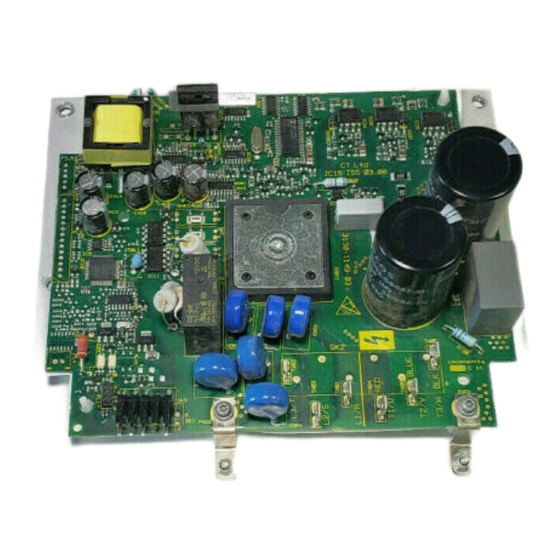
Electrical installation Drive details Figure 4-1 Power connection detail Ground bar or similar Ground L2/S T1/U T3/W connection* T2/V L1/R L3/T Supply ground Metal enclosure Supply ground Fuses Optional ground connection Mains supply *Ground connection must be made using UL listed 4mm (0.157 in) ring lug T1/U terminal (Red wire) T2/V terminal (Blue wire) T3/W Terminal (Black wire) -
Page 12: Ground Leakage
Figure 4-2 Control connections T1 PWM control input (C) (no connection) T3 Fault output (F) T4 Fault return (FR) T5 PWM control return (CR) Fuses/MCB The AC supply to the drive must be installed with suitable protection against overload and short circuits. Failure to observe this requirement will cause risk of fire. WARNING The drive must be grounded by a conductor sufficient to carry the prospective fault current in the event of a fault. -
Page 13: Emc
4.2.1 Use of ground fault circuit interrupter (GFCI) There are three common types of GFCI: Type AC detects AC fault currents Type A detects AC and pulsating DC fault currents (provided the DC current reaches zero at least once every half cycle) Type B detects AC, pulsating DC and smooth DC fault currents •... - Page 14 Figure 4-4 Removal of the internal MOV Plate M3 screw To disconnect the internal MOV: 1. Loosen the plate M3 nut 2. Loosen PCB screw 3. Swivel the link to the position shown 4. Re-tighten M3 nut to 1Nm (8.9 lb in) 5.
- Page 15 Table 4-2 Key to conformity Compliance Frequency Standard Description Limits Application Level Range 79dBuV quasi peak Generic emission 0.15 – 0.50 MHz 66dBuV average standard for the AC Supply EN 61000-6-4:2007 Industrial Lines 73dBuV quasi peak 0.50 – 30 MHz Environment 60dBuV average Product standard...
- Page 16 Figure 4-5 External EMC filter wiring Ground bar or similar Ground Ground L2/S L2/S T1/U T1/U T3/W T3/W connection T2/V T2/V L1/R L3/T Supply ground Supply Input ground Alarm EMC filter device device Optional ground L1/R L3/T L2/S connection Notes: •...
- Page 17 4.3.4 Immunity compliance The level of the drives immunity from conducted and radiated emissions from external sources is summarised below in Table 4-3. Table 4-3 Immunity compliance Standard Type of immunity Test specification Application Level IEC 61000-4-2 Electrostatic 6kV contact discharge Level 3 Module enclosure EN 61000-4-2...
-
Page 18: Control Terminals I/O Specification
Control terminals I/O specification The control circuits are isolated from the power circuits in the drive by basic insulation (single insulation) only. The installer must ensure that the external control circuits are insulated from human contact by at least one layer of insulation (supplementary insulation) rated for use at the AC supply voltage. -
Page 19: Operation
Repairs and replacements Field repairs of the VFD66 Control should not be made. In case of a defective or improperly functioning control, contact your nearest Authorized Johnson Controls/PENN® Distributor or Sales Representative. When contacting your Johnson Controls/PENN distributor, have the model number of the control available. -
Page 20: Technical Specifications
Technical specifications Model VFD66 Drive voltage rating 230Vac, 460Vac @ 60Hz (230Vac, 400Vac @ 50Hz) Output Voltage/Output frequency 230Vac, 460Vac @ 60Hz Switching frequency 3kHz Duty Normal Overload limit 110% overload current for 60s Acceleration/Deceleration 5 s/100Hz Start/Stop Terminal control ≤50m Motor cable lengths °... -
Page 21: Ul Listing Information
UL listing information UL information (For VFD66JCB-1, VFD66KCB-1) The Johnson Control UL file number is E244421. Confirmation of UL listing can be found on the UL website: www.ul.com. 7.1.1 Conformity The drive conforms to UL listing requirements only when the following are observed: •... - Page 22 24-10511-104...
Need help?
Do you have a question about the VFD66JCB-1 and is the answer not in the manual?
Questions and answers