Table of Contents
Advertisement
Quick Links
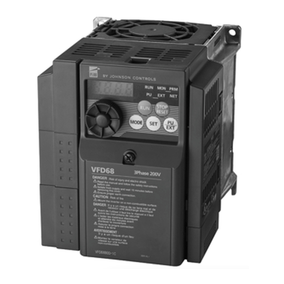
VFD68 Variable Frequency Drive (575 VAC)
Installation Instructions
VFD68Dxx
Introduction . . . . . . . . . . . . . . . . . . . . . . . . . . . . . . . . . . . . . . . . . . . . . . . . . . . . . . . . . . . . . . . .3
North American Emissions Compliance . . . . . . . . . . . . . . . . . . . . . . . . . . . . . . . . . . . . . . . . .3
United States . . . . . . . . . . . . . . . . . . . . . . . . . . . . . . . . . . . . . . . . . . . . . . . . . . . . . . . . . . . . . . . . . . 3
Canada . . . . . . . . . . . . . . . . . . . . . . . . . . . . . . . . . . . . . . . . . . . . . . . . . . . . . . . . . . . . . . . . . . . . . . . 3
Agency Standards Compliance . . . . . . . . . . . . . . . . . . . . . . . . . . . . . . . . . . . . . . . . . . . . . . . . . . . 4
Installation . . . . . . . . . . . . . . . . . . . . . . . . . . . . . . . . . . . . . . . . . . . . . . . . . . . . . . . . . . . . . . . . .4
Checking the Rating Plate. . . . . . . . . . . . . . . . . . . . . . . . . . . . . . . . . . . . . . . . . . . . . . . . . . . . . . . . 4
Selecting a Motor . . . . . . . . . . . . . . . . . . . . . . . . . . . . . . . . . . . . . . . . . . . . . . . . . . . . . . . . . . . . . . 5
Selecting a VFD68 Drive for Controlling Multiple Motors . . . . . . . . . . . . . . . . . . . . . . . . . . . . . . 5
Dimensions . . . . . . . . . . . . . . . . . . . . . . . . . . . . . . . . . . . . . . . . . . . . . . . . . . . . . . . . . . . . . . . . . . . 7
Mounting . . . . . . . . . . . . . . . . . . . . . . . . . . . . . . . . . . . . . . . . . . . . . . . . . . . . . . . . . . . . . . . . . .8
Wiring . . . . . . . . . . . . . . . . . . . . . . . . . . . . . . . . . . . . . . . . . . . . . . . . . . . . . . . . . . . . . . . . . . . .10
Precautions . . . . . . . . . . . . . . . . . . . . . . . . . . . . . . . . . . . . . . . . . . . . . . . . . . . . . . . . . . . . . . . . . . 11
Terminal Screw Torque Specifications . . . . . . . . . . . . . . . . . . . . . . . . . . . . . . . . . . . . . . . . . . . . 12
Branch Circuit Protection . . . . . . . . . . . . . . . . . . . . . . . . . . . . . . . . . . . . . . . . . . . . . . . . . . . . . . . 12
Short Circuit Ratings . . . . . . . . . . . . . . . . . . . . . . . . . . . . . . . . . . . . . . . . . . . . . . . . . . . . . . . . . . . . 12
High-Voltage Wire Size and Maximum Wire Length . . . . . . . . . . . . . . . . . . . . . . . . . . . . . . . . . . 13
Selecting the Correct VFD68 Drive for a Fan Motor . . . . . . . . . . . . . . . . . . . . . . . . . . . . . . . . . . . . 13
Calculating the Maximum Wire Length . . . . . . . . . . . . . . . . . . . . . . . . . . . . . . . . . . . . . . . . . . . . . . 14
Making High-Voltage Wiring Connections . . . . . . . . . . . . . . . . . . . . . . . . . . . . . . . . . . . . . . . . . 15
Making Low-Voltage Wiring Connections . . . . . . . . . . . . . . . . . . . . . . . . . . . . . . . . . . . . . . . . . . 17
Input Wiring Connections. . . . . . . . . . . . . . . . . . . . . . . . . . . . . . . . . . . . . . . . . . . . . . . . . . . . . . . . . 19
Setup and Adjustment . . . . . . . . . . . . . . . . . . . . . . . . . . . . . . . . . . . . . . . . . . . . . . . . . . . . . .20
Correspondences Between Digital and Actual Characters . . . . . . . . . . . . . . . . . . . . . . . . . . . . 20
VFD68 Variable Frequency Drive (575 VAC) Installation Instructions
Refer to the
QuickLIT website
. . . . . . . . . . . . . . . . . . . . . . . . . . . . . . . . . . . . . . . . . . . . . . . . . . . . . . . 5
1
Part No. 24-7664-3116, Rev. D
Issued October 2017
for the most up-to-date version of this document.
Advertisement
Table of Contents

Related Manuals for Johnson Controls Penn VFD68


Summary of Contents for Johnson Controls Penn VFD68
-
Page 1: Table Of Contents
VFD68 Variable Frequency Drive (575 VAC) Installation Instructions VFD68Dxx Part No. 24-7664-3116, Rev. D Issued October 2017 Refer to the QuickLIT website for the most up-to-date version of this document. Introduction ..............3 North American Emissions Compliance . - Page 2 Operation Modes ............. . 20 Mode of Operation Icons .
-
Page 3: Introduction
VFD68 Variable Frequency Drives (575 VAC) Introduction The VFD68 Variable Frequency Drives are designed to provide three-phase motor speed control in a variety of HVACR applications. The VFD68 Drives are factory-configured for condenser fan speed control on HVACR condensing units. You can quickly and easily reconfigure the VFD68 Drives to control variable speed pumps in cooling and heating applications, or to drive variable speed supply fans in VAV applications. -
Page 4: Agency Standards Compliance
See Figure 1, Table 1, and Selecting the Correct VFD68 Drive for a Fan Motor on page 13. Production year and month Rating plate Johnson Controls DATE:XXXX-XX VFD model MODEL Input rating... -
Page 5: Selecting A Motor
Selecting a Motor IMPORTANT: When selecting the motor, do not exceed the maximum output current rating of the VFD68 Drive. Motors used with the VFD68Dxx Drive must: • be AC induction three-phase motors that are UL Recognized and CSA Certified, or equivalent •... - Page 6 • Do not install the modules in airtight enclosures. • Do not install heat-generating devices that may cause the temperature to exceed the ambient operating limit in the same enclosure as the modules. The VFD68 Drive has been approved for use in an enclosure. Approval tests were conducted under the conditions in Table 2.
-
Page 7: Dimensions
Figure 2: VFD68Dxx Maximum Current Output Derating above 50°C Dimensions Figure 3: Dimensions for VFD68Dxx Drives, mm (in.) Table 4: Dimensions for VFD68Dxx Drives, mm (in.) VFD Model VFD68DFM 150 (5-15/16) 138 (5-7/16) 140 (5-1/2) 128 (5-1/16) 136 (5-3/8) VFD68DGM VFD68DHM VFD68DJN... -
Page 8: Mounting
Mounting 1. To remove the front cover, push down on the hooks at Position A and Position B and pull the front cover away from the VFD68 Drive, using the hooks at Position C as supporting points (Figure 4). Figure 4: Release the Hooks and Remove the Front Cover. - Page 9 See Figure 6 and Table 5 for mounting space requirements. 3.7 kW (5 HP) or Less 5.5 to 7.5 kW (7-1/2 to 10 HP) Front Side Front Side Figure 6: Required Clearance for Mounting Inside an Enclosure Table 5: Required Clearance Dimension 3.7 kW (5 HP) or Less 5.5 to 7.5 kW (7-1/2 to 10 HP)
-
Page 10: Wiring
Wiring WARNING: Risk of Electric Shock. Disconnect the power supply before making electrical connections. Contact with components carrying hazardous voltage can cause electric shock and may result in severe personal injury or death. AVERTISSEMENT: Risque de décharge électrique. Débrancher l'alimentation avant de réaliser tout branchement électrique. Tout contact avec des composants porteurs de tensions dangereuses risque d'entraîner une décharge électrique et de provoquer des blessures graves, voire mortelles. -
Page 11: Precautions
IMPORTANT: Do not exceed the VFD68 Drive's electrical ratings. Exceeding the drive electrical ratings can result in permanent damage to the drive and void any warranty. IMPORTANT: Run all low-voltage wiring and cables separate from all high-voltage wiring. Shielded cable is strongly recommended for input (sensor) and analog output cables that are exposed to high electromagnetic or radio frequency noise. -
Page 12: Terminal Screw Torque Specifications
• Prevent VFD-generated EMI from causing functional problems. Do not run the low-voltage signal cables and the high-voltage power cables in parallel with each other, and do not bundle them together. Run low-voltage signal cables as far away as possible from high-voltage power cables. Use shielded cables for the low-voltage signal cables. -
Page 13: High-Voltage Wire Size And Maximum Wire Length
High-Voltage Wire Size and Maximum Wire Length IMPORTANT: Use copper conductors only. Make all wiring in accordance with local, national, and regional regulations. Use UL Listed copper, stranded wire with insulation rated at 75°C (167°F) for wiring the high-voltage supply to the drive (R/L1, S/L2, T/L3) and wiring the high-voltage drive output (U, V, W) to the motor. -
Page 14: Calculating The Maximum Wire Length
Calculating the Maximum Wire Length 1. Use the recommended wire size in accordance with local, national, and regional regulations to determine the electrical resistance of the wire (R) according to Table 10. Table 10: Electrical Resistance by Wire Size Recommended Electrical Resistance of Recommended Electrical Resistance of... -
Page 15: Making High-Voltage Wiring Connections
Making High-Voltage Wiring Connections 1. Push down on the hooks at Position A and Position B and pull it away from the VFD68 Drive, using the hooks at Position C as supporting points (Figure 8). Figure 8: Release the Hooks and Remove the Front Cover 2. - Page 16 Note: Use UL-Listed, copper stranded wire with insulation rated at 75°C (167°F) for wiring the high-voltage supply to the drive (R/L1, S/L2, T/L3) and wiring the high-voltage drive output (U, V, W) to the motor. Jumper R/L1 S/L2 Figure 10: High-Voltage Terminal Block Wiring 5.
-
Page 17: Making Low-Voltage Wiring Connections
Making Low-Voltage Wiring Connections Low-voltage wiring terminals are located underneath the front cover. After you finish making the low-voltage wiring connections, replace the front cover. . Figure 11: VFD68Dxx Drives Connection Information Table 11: VFD68Dxx Drives Low-Voltage Connection Information for the Primary Board (Part 1 of 2) Terminal Signal Type Description... - Page 18 Table 11: VFD68Dxx Drives Low-Voltage Connection Information for the Primary Board (Part 2 of 2) Terminal Signal Type Description Label Relay Output (N.C.) During normal operation, relay contacts B and C are connected (maximum alarm load: 230 VAC, 0.3 A or 30 VDC, 0.3 A). Relay Output (C) Relay output common +5 V...
-
Page 19: Input Wiring Connections
Input Wiring Connections Wire the input device to the analog input terminals and make any necessary parameter adjustments. See Setup and Adjustment on page 20 and Parameter Settings Calculations for Motor Speed vs. Pressure on page 25 for more information. 0.5–4.5 VDC Ratiometric P499 Transducer The default parameter settings (Table 13) on the VFD68 Drive are configured to operate a condenser fan motor on an R410 condensing unit, using a... -
Page 20: Setup And Adjustment
Setup and Adjustment Correspondences Between Digital and Actual Characters The actual alphanumeric characters correspond to the following digital characters displayed on the operation panel: Actual Digital Actual Digital Actual Digital Operation Modes Mode of Operation Icons The VFD68 Drive mode of operation is indicated by the mode of operation icons (labeled PU and EXT) on the drive’s operation panel (Figure 13). - Page 21 • Press to scroll through the parameter codes and to edit parameter setting values. • Press to enter the 3-digit parameter code for viewing and editing. COVER OPENED: Unit indication Operation status indication Setting key Reverse key Mode key RESET STOP/RESET key Forward key STOP/RESET key UP/DOWN key...
-
Page 22: Vfd68Dxx Drive Parameters
Table 15: Unit Indications and Operating Status Indications (Part 2 of 2) Indication Description Lit to indicate the PU operation mode Lit to indicate the external operation mode VFD68Dxx Drive Parameters You can use the default parameter setting with the P499RxP-107C Transducer and R410a refrigerant within a range of operation that depends on the specific model of P499 Transducer selected. - Page 23 Table 16: Parameter Descriptions for VFD68Dxx Drives (Part 2 of 2) Parameter Description Settings Default Indication Setting on Monitor P. 36 Frequency Jump 3B: To avoid resonance noise caused by 0 to 400 Hz, 9999 9999 natural frequency of mechanical system, enter frequency just above noisy frequency 3.
-
Page 24: Frequency And Motor Speed
Frequency and Motor Speed Frequency (Hz) is an expression of motor speed (RPM) on the VFD. Figure 14 and Figure 15 show how the drive operating frequency is related to the speed (RPM) of the motor. Figure 14: Frequency and Motor Speed (60 Hz) Figure 15: Frequency and Motor Speed (50 Hz) VFD68 Variable Frequency Drives (575 VAC) -
Page 25: Parameter Settings Calculations For Motor Speed Vs. Pressure
The drive can be configured to display operating frequency (Hz) or motor speed (RPM). To display motor speed (RPM) instead of operating frequency (Hz), set P. 37 to the rated motor RPM value. See Adjusting the Default Parameters on page 26. Parameter Settings Calculations for Motor Speed vs. -
Page 26: Adjusting The Default Parameters
Adjusting the Default Parameters CAUTION: Risk of Property Damage. Do not apply power to the system before checking all wiring connections. Short circuited or improperly connected wires may result in permanent damage to the equipment. MISE EN GARDE : Risque de dégâts matériels. Ne pas mettre le système sous tension avant d'avoir vérifié... -
Page 27: Exit The Parameter Adjustment Mode
18. Press and hold for two seconds to set the P.90xa value and show the actual input % for P.90xb. 19. Press once to view the default setting (38% for P.902b). Press to change the value. 20. Press and hold for two seconds to set the new value. - Page 28 Table 17 defines the indication categories. Table 18 provides descriptions of the individual indicator messages. Table 17: Indication Categories on the Operation Panel Display Indication Description Category Error message A message regarding operational or setting errors displays. The VFD continues operating. Warning The VFD continues operating.
- Page 29 Table 18: Indicator Messages (Part 2 of 2) Operation Panel Indication Name Fault E.OC1 Over-current trip during acceleration E.OC2 Over-current trip during constant speed E.OC3 Over-current trip during deceleration or stop E.OV1 Regenerative over-voltage during acceleration E.OV2 Regenerative over-voltage trip during constant speed E.OV3 Regenerative over-voltage trip during deceleration...
-
Page 30: Resetting The Vfd68 Drive
Resetting the VFD68 Drive WARNING: Risk of Personal Injury. Before you reset the VFD68 Drive, verify that all persons are clear of the controlled equipment. Resetting the VFD68 Drive may immediately start the controlled equipment, and failure to verify that all persons are clear of the controlled equipment before resetting the VFD68 Drive may result in severe personal injury or death. -
Page 31: Restarting The Motor After It Has Stopped
Restarting the Motor After It Has Stopped To restart the motor after a controlled stop, disconnect the supply power from the drive for at least 30 seconds and then reconnect the supply power to the drive. If it is not easy to disconnect the supply power from the drive, follow these steps: 1. -
Page 32: Technical Specifications
Metasys® and Johnson Controls® are registered trademarks of Johnson Controls, Inc. of their respective owners. © Copyright 2017 by Johnson Controls. All rights reserved. All other marks herein are the marks of their respective owners. © 2011 Johnson Controls, Inc. VFD68 Variable Frequency Drives (575 VAC) Published in U.S.A.
Need help?
Do you have a question about the Penn VFD68 and is the answer not in the manual?
Questions and answers