Advertisement
Advertisement

Related Manuals for Luxman L-505u


Summary of Contents for Luxman L-505u
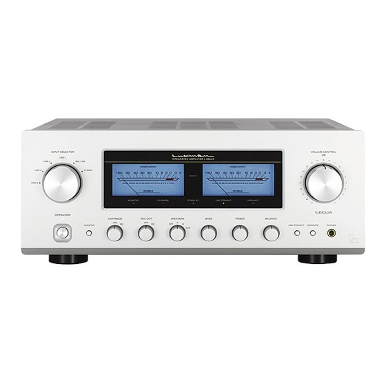
- Page 1 INTEGRATED AMPLIFIER L-505u Owner`s Manual...
-
Page 2: Table Of Contents
Contents Precautions ........................3 Names and Functions ....................4 Connections ........................10 Operations ........................12 How to use remote control ..................14 L-505u Block Diagram ....................15 Specifications......................16 Before asking for repair services ................17... -
Page 3: Precautions
Precautions Installation place Precautions in connecting Protection circuit with other components This unit shall be installed in a well- This product is equipped with the pro- ventilated and effectively heat- When connecting this unit to input tection circuit that is activated upon released place. -
Page 4: Names And Functions
Names and Functions Front panel 1. Power switch 3. Input selector (stand by/on) (INPUT SELECTOR) Toggles the power on and off. Selects an input device from the When wiring or connection is per- devices such as a CD/DVD player formed, be sure to turn off this and tuner connected to each input switch. - Page 5 Names and Functions 5. Phono MC cartridge on/off 9. Volume control switch (phono MC) (VOLUME CONTROL) Changes the gain level of the Adjusts the sound volume. Sound equalizer amplifier (amplifier circuit is not generated when this control required to play an analog record). is rotated counterclockwise to the MC : ON is selected by pressing end, and then, the sound volume...
- Page 6 Names and Functions Front panel 11. Subsonic (subsonic) 13. Balance (BALANCE) Cuts ultra-low frequencies out of Adjusts the balance of sound vol- audible range to prevent ultra-low ume between right and left chan- range noise from adversely affecting nels. audible range. This function is signif- Rotating this switch counterclock- icantly effective especially when a wise causes the left sound volume...
- Page 7 Names and Functions 14. Tone control for treble 17. Speaker selector (TONE CONTROL, treble) (SPEAKERS) Controls the frequency characteris- Selects either of 2 speaker sys- tics in the high-frequency range. tems, A or B, located at the rear When this switch is set to the cen- panel.
- Page 8 Names and Functions Rear panel 24 25 20. Signal ground 23. Recorder input/output (ground terminal) terminals (REC-1, REC-2) (SIGNAL GROUND) Connects the audio input/output of Is a ground terminal for devices to a recorder. The audio input of a be connected to this unit. This ter- recorder is connected to REC OUT, minal is used to reduce noise when and the audio output of a recorder...
- Page 9 Names and Functions 26. AC inlet (AC IN) 28. LINE input terminals (balance) Connects the accessory power (BALANCED LINE) cable. The power shall be supplied from a household wall socket. Are the balance type input termi- nals of the LINE level for an XLR 27.
-
Page 10: Connections
Connections CD/SACD PLAYER CD/DVD • A PLAYER ULTIMATE FIDELITY : A LIMITED EDITION CRAFTED BY LUXMAN CORPORATION, JAPAN digital POWER video off FE DAC data off remote FL off RECORDER RECORD PLAYER – – – – SPEAKER SYSTEM ( A ) - Page 11 Connections How to connect record player Connection to REC OUT terminal (recording) Connect between the output terminal When the sound source from the of an analog record player and the various input devices is repro- PHONO terminal of this unit with 2 (R duced, which are connected to the and L) pin-plug cables.
-
Page 12: Operations
Operations Before operations How to operate the tone control 1. Ensure that the connections are cor- rectly performed. (Normal playback This unit has the tone control function cannot be achieved with wrong con- for the low-frequency and high-fre- nection of R, L, +, or -.) quency ranges. - Page 13 Operations How to record a source Procedure of timer-controlled playing 1. Select a source to be recorded with the recording selector. 1. Turn on the power switch to acti- * For dubbing: vate this unit. Selection of rec-1; rec-1 → rec-2 2.
-
Page 14: How To Use Remote Control
How to use remote control 30. Mute switch Remote control Activates the mute function and The remote control shall be aimed at blinks the power-on indicator result- the remote sensor of this unit within ing in no sound generated. the specified angle range shown in the Pressing this button again to set illustration when used. -
Page 15: L-505U Block Diagram
L-505u Block Diagram... -
Page 16: Specifications
Specifications Continuous power output 100W + 100W (8Ω) 140W + 140W (4Ω) Total harmonic distortion 0.008% (8Ω,1kHz both channels simultaneous drive, line straight on) 0.04% (8Ω,20 ∼ 20kHz, both channels simultaneous drive, line straight on) Pre-amplifier PHONO (MM) : 2.5mV / 47kΩ Input sensitivity/input impedance PHONO (MC) : 0.3mV / 100Ω... -
Page 17: Before Asking For Repair Services
Before asking for repair services While the unit is used, an unusual phenomenon may be confused as a malfunction for a certain reason. Prior to asking us for repair services, please check the table below and read the instruction manual for the subsidiary devices. If the cause of the malfunction cannot be identi- fied, please contact your dealer. - Page 18 MEMO...
- Page 19 AG00987C44A LUXMAN CORPORATION, JAPAN Printed in Japan...
Need help?
Do you have a question about the L-505u and is the answer not in the manual?
Questions and answers