Kirsch LABEX 105 PRO-ACTIVE Operating Instructions Manual
Hide thumbs
Also See for LABEX 105 PRO-ACTIVE:
- Operating instructions manual (78 pages) ,
- Service manual (56 pages) ,
- Operating instructions manual (79 pages)

Related Manuals for Kirsch LABEX 105 PRO-ACTIVE


Summary of Contents for Kirsch LABEX 105 PRO-ACTIVE
- Page 1 Operating instructions Refrigerator/freezer LABEX® series Read instruction manual before starting work!
- Page 2 Philipp KIRSCH GmbH Im Lossenfeld 14 77731 Willstätt-Sand GERMANY Telephone: +49 781 9227-0 Fax: +49 781 9227-200 Email: info@KIRSCH-medical.de Internet: www.KIRSCH-medical.de D1005_05.21_Operating instructions LABEX version 2, en_GB © Philipp KIRSCH GmbH 2021 Refrigerator/freezer LABEX® series 27.05.2021...
- Page 3 Supplemental directives About this instruction manual This instruction manual was created for the product “Refrigerator/ freezer” (hereafter referred to as “unit”). Persons who work with the unit must have carefully read and understood this instruction manual before any work begins. To ensure safe working conditions, all specified safety warnings and instructions in this instruction manual must be observed.
- Page 4 Internet www.kirsch-medical.de Orders are accepted during business hours. More information If you have questions or comments regarding this instruction manual or the unit, please contact your authorised regional spe- cialist dealer or contact KIRSCH directly. Refrigerator/freezer LABEX® series 27.05.2021...
-
Page 5: Table Of Contents
Table of contents Table of contents Product description............7 1.1 Unit overview..............7 1.2 Display and control elements........11 1.2.1 Design of the display and control unit...... 11 1.2.2 Function of the key switch ........11 1.2.3 Function of buttons and displays......11 1.3 Scope of delivery............ - Page 6 Table of contents 6.2.1.1 Function of the target temperature....... 36 6.2.1.2 Displaying and changing the target temperature.. 36 6.2.2 Temperature warning limits........38 6.2.2.1 Function of the temperature warning limits... 38 6.2.2.2 Displaying and changing the temperature warning limits..............39 6.2.3 Adjusting the humidity..........
-
Page 7: Product Description
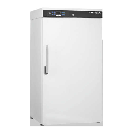
Product description Unit overview Product description 1.1 Unit overview ® Model LABEX (example) Fig. 1: Laboratory refrigerator (housing) Key switch Ä Chapter 1.2 “Display and control Display and control unit elements” on page 11 Door lock Door handle Adjustable feet 27.05.2021 Refrigerator/freezer LABEX®... - Page 8 Product description Unit overview Fig. 2: Laboratory refrigerator (interior) Circulation cooling Support rail Supports Drawer Melt water container Cooling machine Refrigerator/freezer LABEX® series 27.05.2021...
- Page 9 Product description Unit overview ® FROSTER LABEX model (example) Fig. 3: Laboratory freezer (housing) Key switch Ä Chapter 1.2 “Display and control Display and control unit elements” on page 11 Door lock Door handle Adjustable feet 27.05.2021 Refrigerator/freezer LABEX® series...
- Page 10 Product description Unit overview Fig. 4: Laboratory freezer (interior) Circulation cooling Support rail Supports Drawer Melt water container Cooling machine Refrigerator/freezer LABEX® series 27.05.2021...
-
Page 11: Display And Control Elements
Product description Display and control elements > Function of buttons and displays 1.2 Display and control elements 1.2.1 Design of the display and control unit Fig. 5: Display and control unit Key switch Display and control unit (variable key assignment) USB port 1.2.2 Function of the key switch Tab. - Page 12 Product description Display and control elements > Function of buttons and displays Tab. 2: Buttons Button Description Function [Max.] Display maximum value of temperature memory. [Min.] Display minimum value of temperature memory. Reset temperature memory. [Reset] Switch off buzzer. [Temperature warning Read upper temperature warning limit.
-
Page 13: Scope Of Delivery
Product description Interfaces Depending on the version, certain buttons have a multiple function in combination with other buttons. Tab. 3: Displays Display Description Function “Defrosting” Defrosting is active. “Humidity” Humidity is active (temperature consistency improved, humidity high). “SuperFrost” SuperFrost is active. “Alarm”... -
Page 14: Unit Functions
Product description Unit functions > Cooling Tab. 4: Interfaces Interface Module LAN interface PC-KIT-NET (optional) USB port PC-KIT-STICK Potential-free alarm contact Remote warning system (for example GSM-MODUL or con- nection to building control system (see circuit diagram on unit)) For information about connecting the modules to the unit, see the relevant product documentation. -
Page 15: Superfrost Function
Product description Unit functions > Defrosting Circulation cooling is set to continuous operation and is switched off automatically when the door is opened. The LABEX ® 105 PRO-ACTIVE, LABEX ® PRO-ACTIVE and FROSTER LABEX ® 96 PRO- ACTIVE models do not have circulation cooling. Condenser The condenser transfers the generated thermal energy to the ambient air. -
Page 16: Temperature Display
Product description Unit functions > Temperature memory Empty the melt water container manually at regular intervals Ä “Melt water container” on page 16. When the defrosting process is active, the “Defrosting” LED dis- play lights up on the Display. Additional defrosting In addition to automatic defrosting, it is possible to start the defrosting process manually. -
Page 17: Temperature Monitoring With Pc-Kit-Stick
Product description Battery The temperature memory can be retrieved and erased manually Ä Chapter 7.3 “Retrieving/erasing the temperature memory” on page 43. 1.5.6 Temperature monitoring with PC-KIT-STICK The temperature memory of the unit documents the maximum and minimum temperature values. PC-KIT-STICK is the easiest method of automatic temperature documentation. -
Page 18: Additional Unit Components
Product description Additional unit components > Temperature documentation The battery does not supply the unit! The battery only provides power to the tempera- ture monitoring. The battery does not provide a back-up to the unit and therefore ensure that the interior temperature is maintained. -
Page 19: Lockable Glass Door
The user/owner may have to check for compatibility. 1.7.2 Lockable glass door Door lock Your unit can be equipped with a lockable glass door. For more information on installing the glass door, contact KIRSCH. 27.05.2021 Refrigerator/freezer LABEX® series... -
Page 20: Accessories
Accessories GSM module Accessories The unit can be equipped with the following accessories: GSM module 2.1 GSM module The GSM module is used to forward alarm messages to a mobile or fixed-line telephone network via text message. To operate the GSM module you need a SIM card (not supplied). -
Page 21: Safety
Safety Symbols in this instruction manual Safety This section provides an overview of all important safety aspects for optimal protection of patients and staff, and for safe and trouble-free operation of the unit. Non-compliance with the instructions and safety warnings in this instruction manual can cause considerable risks. -
Page 22: Purpose
Safety Purpose Other markings Mark Explanation Step-by-step instructions ð Results of actions References to sections in this instruction manual Lists without a specified order References to the instruction manuals for accessories and optional parts 3.2 Purpose The laboratory refrigerator and the laboratory freezer are equipped with an explosion-proof interior (hereafter referred to as “potentially explosive area”). -
Page 23: Foreseeable Misuse
Safety Residual risks 3.3 Foreseeable misuse The unit is not designed for domestic use. The unit is used for commercial storage of chilled goods in line with its intended pur- pose. Do not use the unit to cool warm goods. Do not store chilled goods in the unit if their cooling chain was interrupted during delivery or stock transfer. - Page 24 Safety Residual risks Electrostatic discharge DANGER! Danger due to electrostatic discharge! Electrostatic charging and discharging endangers or invalidates the function of the explosion-pro- tected interior. Make sure that no electrostatic discharge can take place in the interior. – Before working in the interior of the unit, touch an earthed item (e.g.
- Page 25 Safety Residual risks Hot surface WARNING! Danger due to hot surface! The marked areas of the unit can cause severe skin injuries if touched. – Do not touch areas of the unit marked in this way. – These areas are very hot and can still cause burns several hours after the unit has been switched off.
-
Page 26: Safety Markings
Safety Safety markings Blocked interior ventilation CAUTION! Danger of damage and injury due to blocked interior ventilation! Without adequate ventilation of the cooling machine the air circulation inside the unit is no longer ensured. This can lead to a temperature drop inside the unit, which can damage the chilled goods. -
Page 27: Staff Qualification
The system/network administrator performs the following duties: Installing KIRSCH-DATANET Integrating the unit in the network The system/network administrator has been authorised by the owner to manage the users of the software and to make settings to the software. -
Page 28: Personal Protective Equipment
Safety Personal protective equipment The unit officer meets the following requirements: The unit officer knows the intended purpose, the foreseeable misuse and the residual risks of the unit. The unit officer is familiar with the instruction manual and all other safety-related documents. The unit officer has been instructed in the technically correct and safe handling of the unit. - Page 29 Safety Personal protective equipment NOTICE! Suitable ESD protective equipment should be used when using the unit, in order to protect the stored chilled goods. This equipment must comply with the EN 61340-5-1 standard. Chemical-resistant protective gloves Chemical-resistant protective gloves protect the hands from aggressive chemicals.
-
Page 30: Transport And Decommissioning
Transport and decommissioning Unit transport Transport and decommissioning 4.1 Unit transport On delivery, the unit is transported after consultation with the spe- cialist dealer. When transporting the unit during a change of location while the unit is still operating, observe the following safety instructions. Safety during transport WARNING! Danger of crushing injuries from falling unit! -
Page 31: Final Decommissioning Of The Unit
Transport and decommissioning Final decommissioning of the unit NOTICE! Danger of damage to the melt water container! The units in the table below are equipped with a melt water container on their underside, which can be damaged by incorrect transport: –... -
Page 32: Putting The Unit Back Into Operation
Transport and decommissioning Putting the unit back into operation 4.3 Putting the unit back into operation Ä Chapter 8 Putting the unit back into operation Before recommissioning, clean and disinfect the unit “Cleaning and disinfection” on page 51. Plug in power plug. Insert unit key in key switch. -
Page 33: Set-Up, Installation And Connection
Set-up, installation and connection Setting up the unit Set-up, installation and connection 5.1 Setting up the unit Set-up When setting up the unit, observe the following set-up conditions: Ensure an ambient temperature between +10 °C – +38 °C (as per climate class SN and ST). Ensure an ambient temperature between +10 °C –... -
Page 34: Installing The Unit
Installing Have the unit installed only by staff qualified for the task. If in Ä “Manufacturer’s address” on page 4. doubt, contact KIRSCH Install the unit as shown in the installation drawing provided. 5.3 Connecting the unit Connecting The unit is designed according to protection class I and protection type IP 20 and is ready to be plugged in. -
Page 35: Commissioning
Commissioning Programming the unit Commissioning Personnel: Unit officer 6.1 Activities during commissioning Commissioning sequence WARNING! Danger of damage and injury due to commis- sioning by unqualified staff! If commissioning is performed incorrectly by unqualified staff, serious damage to the chilled goods can result, which in turn can lead to serious injuries. -
Page 36: Target Temperature
The target temperature specifies the temperature at which the unit is operated to store the chilled goods in optimal conditions. The target temperature of the unit is preset by KIRSCH. Changes to the target value do not change the temperature warning limits. These are adjusted Ä... - Page 37 The unit will not reach the new target value immediately after the change is made. Monitor the temperature progression on the Display or using optional temperature documentation (e.g. KIRSCH-PC-KIT). Read the current temperature and monitor the subsequent temperature progression until the target temperature is reached. 27.05.2021...
-
Page 38: Temperature Warning Limits
Commissioning Programming the unit > Temperature warning limits Consequences of modified target temperature As soon as the target temperature is reached, the temperature warning limits must be adjusted so that the target temperature is above or below the temperature warning limits. Otherwise the tem- Ä... -
Page 39: Displaying And Changing The Temperature Warning Limits
Commissioning Programming the unit > Temperature warning limits Temperature warning limits ® ® Tab. 6: Temperature warning limits for LABEX and FROSTER LABEX Model Lower temperature Target temperature Upper temperature warning limit warning limit +1 °C +5 °C +10 °C LABEX ®... - Page 40 Commissioning Programming the unit > Temperature warning limits Changing the temperature warning limits Recommended temperature warning limits The temperature warning limits must not be the same as the target temperature. Set the temperature limits as follows: – Upper temperature warning limit: at least 3 °C higher than the target temperature –...
-
Page 41: Adjusting The Humidity
Commissioning Programming the unit > Adjusting the humidity 6.2.3 Adjusting the humidity Overview of units with adjustable ® ® LABEX 288 PRO-ACTIVE LABEX 288 ULTIMATE humidity ® ® LABEX 340 PRO-ACTIVE LABEX 340 ULTIMATE ® ® LABEX 468 PRO-ACTIVE LABEX 468 ULTIMATE ®... -
Page 42: Operation
Operation Switching off the unit Operation Personnel: User 7.1 Switching on the unit Insert the key into the key switch. Turn unit key to position “1”. ð The Display shows the interior temperature. Remove the key and store it so it is protected against unau- thorised access. -
Page 43: Retrieving/Erasing The Temperature Memory
Operation Retrieving/erasing the temperature memory Only switch the stocked unit off for short periods! To protect the chilled goods, only switch the stocked unit off for short periods. To shut down the unit for a longer period, proceed Ä Chapter 4.2 “Final decommis- as described in sioning of the unit”... -
Page 44: Switching On The Superfrost Function
Operation Setting up PC-KIT-NET (optional) 7.4 Switching on the SuperFrost function The lower temperature warning limit of the unit is set to the lowest value Ä Chapter 6.2.2 “Temperature warning limits” on page 38. Switching on SuperFrost Press button [SuperFrost]. ð... - Page 45 Operation Setting up PC-KIT-NET (optional) For temperature monitoring via the network, the KIRSCH-DATANET software (version 5.0 or higher) must be installed (complete assembly and connection manual is supplied with PC-KIT-NET). Setting up the IP address on the unit Every unit needs its own IP address that is not yet in use in your local network.
- Page 46 Operation Setting up PC-KIT-NET (optional) Setting up the subnet mask on the unit At the factory, the subnet mask is: 255.255.255.0 Insert unit key in key switch. Set unit key to “P”. Press and hold [Max.] and [Min.] simultaneously for four sec- onds.
- Page 47 Operation Setting up PC-KIT-NET (optional) Setting up the IP address of the standard gateway on the unit The standard gateway of each unit needs its own IP address that is not yet in use in your local net- work. At the factory, the IP address of the standard gateway is set to: 192.168.0.200 Insert unit key in key switch.
- Page 48 18 and “Assembly and con- nection manual – PC-KIT-STICK/PC-KIT-NET”). The KIRSCH-DATANET software (version 5.0 or higher) has been installed on the local PC or local network. Ä Chapter 7.2 “Switching off the unit” Switch off the unit on page 42.
-
Page 49: Stocking The Unit
Operation Stocking the unit The first two displayed digits “00” are not part of the MAC address. Press [Min.] to select the next parameter ð The next digits of the MAC address are displayed. At levels L72 to L75, repeat step 5 until the MAC address has been completely read out. - Page 50 Operation Stocking the unit Before and during stocking, comply with the applicable regula- tions on personal hygiene. Before and during stocking, comply with the safety requirements relevant for the type of chilled goods. Stocking the unit CAUTION! Danger of injury from broken drawers or shelves and falling chilled goods after over- loading! The carrying capacity of the shelves and drawers...
-
Page 51: Cleaning And Disinfection
Using other disinfectants If disinfectants other than those mentioned above are used, test them at an inconspicuous location before their first use. Use only acid-free disinfectants. If in doubt, contact KIRSCH. Cleaning and disinfecting the unit Protective equipment: Chemical-resistant protective gloves CAUTION! - Page 52 Cleaning and disinfection CAUTION! Danger of damage due to interrupted cooling chain during stock transfer! If the cooling chain of the chilled goods is inter- rupted by a stock transfer, the prescribed storage conditions are no longer met. This can damage the chilled goods.
- Page 53 Cleaning and disinfection Put drawers and shelves back in the unit. Wipe the door seal only with clear water and rub until thor- oughly dry. Ä Chapter 7.1 “Switching on the unit” Switch on the unit on page 42. Cleaning the housing Painted housing Treat the housing with cleaning and care products for painted surfaces.
-
Page 54: Maintenance
Maintenance Safety inspection Maintenance Interval Maintenance work At least every 6 months Check the condenser Ä Chapter 9.1 “Safety inspection” on page 54. 9.1 Safety inspection Perform safety inspection every two years! The unit should be inspected by the owner in line with DGUV regulation 3 (formerly BGV A3). - Page 55 Maintenance Safety inspection Visual inspection Check the entire unit for completeness, correct set-up and damage. Check the following parts of the unit individually for damage: Door handle Interior Door seal If there is damage and functionality is not ensured, decom- mission the unit and contact the service department Ä...
- Page 56 Maintenance Safety inspection Wait until the warning limit is exceeded and the buzzer sounds. ð The Display alternates between the current temperature and the two error messages (upper and lower tempera- ture alarm). Turn unit key to position “1”. ð The test function is completed, the electronic delay is switched on again.
-
Page 57: Alarms
Alarms Alarm functions Alarms 10.1 Alarm functions Alarm functions If a function of the unit is faulty or defective, an alarm is triggered. Every alarm is displayed visually as well as acoustically. The display alternates between the visual alarm and the tempera- ture. -
Page 58: Handling Alarms
Alarms Handling alarms Alarm function Display Buzzer Cause Measure Alarm in case of The power supply Inform the service depart- defective battery for the temperature ment. documentation has Replace the battery failed. Ä “Service contact” The alarm function on page 4. has failed. -
Page 59: Status Displays And Error Messages
(e.g. electric shocks) and damage (e.g. fire, damage to chilled goods). – Have repairs performed by the service depart- ment. – Use KIRSCH replacement parts. – Do not make independent additions or changes to the unit. – If in doubt, contact KIRSCH. 27.05.2021 Refrigerator/freezer LABEX® series... - Page 60 Status displays and error messages Error messages Transferring chilled goods NOTICE! Danger to chilled goods due to defective or faulty unit! A defect or fault in the unit means that its cooling performance is no longer ensured. Reduced cooling performance can cause considerable damage to chilled goods.
- Page 61 Perform the recommended measures. Acknowledge the alarm messages. For repairs, contact the service department: The following company has been commissioned and authorised by KIRSCH to provide service for the unit: Ä “Service contact” on page 4 CAUTION! Danger of damage due to interrupted cooling...
- Page 62 Status displays and error messages Error messages Tab. 11: Error messages of the unit Unit key Display Buzzer Description Measure required Sensor X: Error or short circuit in the rel- Contact the service depart- evant sensor. ment. The cryostat is running in the emergency program.
- Page 63 Status displays and error messages Error messages Unit key Display Buzzer Description Measure required Synchronisation error: Set key switch to “0”. Synchronisation error between Unplug power plug and switch control unit and monitoring cir- Ä Chapter 7.1 on again cuit. “Switching on the unit”...
- Page 64 Status displays and error messages Error messages Unit key Display Buzzer Description Measure required View and check the tempera- Temperature alarm (low) ture warning limit Ä Chapter 6.2.2.2 “Displaying and The lower temperature changing the temperature warning limit is reached or warning limits”...
-
Page 65: Decommissioning And Disposal
Decommissioning and disposal Disposing of the unit Decommissioning and disposal 12.1 Decommissioning unit Decommissioning Switch off unit. Transfer chilled goods to new location. Unplug power plug. Cut through connecting cable. Remove or destroy locks. Remove door. 12.2 Disposing of the unit Disposing of the battery ENVIRONMENT! Danger to the environment due to incorrect dis-... - Page 66 Decommissioning and disposal Disposing of the unit Disposing of the unit ENVIRONMENT! Danger to the environment due to incorrect dis- posal of the unit! If substances hazardous to the environment are handled incorrectly, and especially if they are dis- posed of incorrectly, this can cause serious damage to the environment.
-
Page 67: Appendix
Appendix Appendix Depending on the model, the appendix contains the following appli- cable documents: Declaration of conformity Technical data Installation drawing 27.05.2021 Refrigerator/freezer LABEX® series... -
Page 68: Declaration Of Conformity
Appendix Declaration of conformity 13.1 Declaration of conformity EC Declaration of Conformity Philipp Kirsch GmbH Im Lossenfeld 14 77731 Willstätt-Sand Germany declare that the devices described below comply with the protection requirements of the directives and standards below at the time that the devices were placed on the market. - Page 69 Serial numbers Manufacturer Device category Type from serial number onwards ® FROSTER LABEX 96 PRO-ACTIVE KIRSCH Freezer 095 31 25000 ® FROSTER LABEX 96 PRO-ACTIVE KIRSCH Freezer 095 05 25000 ®...
-
Page 70: Technical Data
Appendix Technical data 13.2 Technical data LABEX® 105 LABEX® 288 LABEX® 340 LABEX® LABEX® 520 465**/468 PRO-ACTIVE PRO-ACTIVE/ PRO-ACTIVE/ PRO-ACTIVE/ PRO-ACTIVE/ ULTIMATE* ULTIMATE* ULTIMATE* ULTIMATE* Capacity in litres Temperature setting +2 to +15 +0 to +15 +0 to +15 +0 to +15 +0 to +15 approx. - Page 71 Appendix Technical data LABEX® 105 LABEX® 288 LABEX® 340 LABEX® LABEX® 520 465**/468 PRO-ACTIVE PRO-ACTIVE/ PRO-ACTIVE/ PRO-ACTIVE/ PRO-ACTIVE/ ULTIMATE* ULTIMATE* ULTIMATE* ULTIMATE* Net/gross weight in 46 / 50 72 / 85 93 / 105 112 / 125 120 / 148 Noise emission (for Ecool R600a) in 36**...
- Page 72 Appendix Technical data LABEX® 720 FR LABEX® FR LABEX® FR LABEX® FR LABEX® PRO-ACTIVE/ PRO-ACTIVE PRO-ACTIVE/ PRO-ACTIVE/ PRO-ACTIVE/ ULTIMATE* ULTIMATE* ULTIMATE* ULTIMATE* Shelf size (WxD) in 59 x 65 43 x 36 57 x 42 59 x 65 59 x 65 Clear drawer dimen- sion (WxDxH) in cm Max.
-
Page 73: Installation Drawing
Appendix Installation drawing 13.3 Installation drawing Fig. 11: Installation drawing for LABEX® 105 PRO-ACTIVE 27.05.2021 Refrigerator/freezer LABEX® series... -
Page 74: Index
Index Index Drawers ......13 About this instruction manual ....3 Additional defrosting . - Page 75 Index Protective equipment ....28 TCP/IP module ..... . 13, 44 Protective gloves .
Need help?
Do you have a question about the LABEX 105 PRO-ACTIVE and is the answer not in the manual?
Questions and answers