Table of Contents
Advertisement
Quick Links
Advertisement
Table of Contents

Subscribe to Our Youtube Channel
Related Manuals for CAME SALOON Series


Summary of Contents for CAME SALOON Series
- Page 1 SWING GATE 2 0EN TURNSTILE INSTALLATION MANUAL PSEPOS00-PSEPSS00 English...
-
Page 2: Read Carefully
Warning Sings (e.g. gate plate). (i.e. that for which it was expressly built for). Any other use is Special instructions and to be considered dangerous. Came Cancelli Automatici S.p.A. advice for users is not liable for any damage resulting from improper, wrongful •... - Page 3 THIS PAGE LEFT INTENTIONALLY BLANK THIS PAGE LEFT INTENTIONALLY BLANK...
-
Page 4: Legend Of Symbols
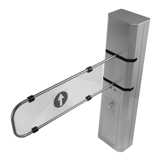
4 Description 4.1 Turnstile This product is designed and built by CAME Cancelli Automatici S.p.A. in compliance with the current safety legislation. Bidirectional, motorised swing gate, made entirely of varnished AISI 304 Inox steel with removable upper cover to access the command logic and a small door with lock to access where it is secured to the ground. -
Page 5: Description Of Parts
4.3 Description of parts 1. Cabinet 2. Wing 3. Top cover 4. Lid 5. Lock 6. Gearmotor 7. Command board 8. Cover screw 9. Wing screw 10. Thrust meter 4.4 Dimensions (mm) 1020... -
Page 6: Typical Applications
5 Typical applications Warning: always have an emergency exit and a disabled persons exit. Standard Double wing gate turnstile Command activated Command activated automatic opening with automatic opening with sensor activated closing, sensor activated closing, right-hand column left-hand column Sensor activated Sensor activated automatic opening with automatic opening with... -
Page 7: Preliminary Checks
6 Installation Only skilled, qualified staff must perform the installation, in full compliance of the current legislation. 6.1 Preliminary checks Before installing the automated device, please • Set up a proper omnipolar cut-off device, with contacts more than 3 mm apart, and power source isolation; •... - Page 8 6.4 Setting up the spot and securing the turnstile to the ground Warning: to install this at least two or three people are needed. Use hoisting equipment to move and position the turnstile. When securing, the turnstile may be unstable and could tip over, so be careful not to lean onto it until securing in complete. - Depending on the transit opening measurements, choose where to position the turnstile and any accessories.
- Page 9 - Position the turnstile along the gussets and run any cable conduits through the central hole. Using a ratching driver, secure the turnstile to the ground. - Remove the top cover by loosening the four screws.
- Page 10 - Insert the wing into holes in the main shaft of the mechanism. - Secure the wing with its screws...
-
Page 11: Electrical Wiring
7 Electrical wiring Distribute the electrical cables (see table “Cable types and sections”) as illustrated in the picture below. Power up the command board via the Pre-drilled cable hole on the plate. power supply unit Power supply unit 24DC Hole Cable gland Hole Running the power cable (alternatively to the plate... -
Page 12: Control Panel
8 Control panel 8.1 General description The control panel is powered by 24V D.C. on terminals 1-8, via The defi nable command and control functionalities are: off board power supply unit. - Clockwise action - Counter-clockwise action The 24V current emitted by the board is of the SELV type. WARNING: before doing any work inside the equipment, cut off The command and control devices and accessories are 24V D.C.. - Page 13 Connecting devices to the control panel Blue Black Brown Thrust meter Black SERVIZIO 3 4 5 6 7 8 24V D.C. gearmotor Connecting complementary devices to the command panel N.O. contact closing photocell. Activates the closing wing Opening device N.O. (button 22-23.
- Page 14 Two-way extra bright LED traffi c light Buzzer Supplementary buzzer for enhanced acustic signal Contact output 12V D.C. – 100mA 8.4 Selecting functions (Dip switches) « Dips 1, 2 and 3 » The wing stays open for 3 seconds minimum to allow people passage. If you want to increase this time interval set Dip switches 1, 2 and 3 as shown in the table below: DIP 1 DIP 2...
- Page 15 9.4 Securing the cover and lid IMPORTANT: before programming, reassemble the turnstile making sure the electric cables do not obstruct the mechanical parts. 1) Position the top cover and tighten the screws. 2) Carefully position the lid and close it.
-
Page 16: Safety Instructions
9 Safety instructions Important general safety instructions This product must be only used for its specific intended purpose. Any other use is wrongful and therefore dangerous. The manu- facturer is not liable for any harm or damage caused by improper, wrongful or unreasonable use. Danger voltage running through parts Danger Hands could be crushedr Transit prohibited during operation. - Page 17 Two-way single-passage endpoint programming procedure - Set Dip switch 5 to ON. Press P1 button and wait for confi rmation beep SERVIZIO SERVIZIO 3 4 5 6 7 8 3 4 5 6 7 8 - Shortcircuit terminals 24-25, the wing will move counter clockwise. Keep terminals shorted until chosen endpoint “A” is reached. Press P1 again and wait for confi...
- Page 18 - Shortcircuit terminals 22-23, the wing will move clockwise. Keep terminals shorted until chosen endpoint “C” is reached. Press P1 again and wait for confi rmation beep. SERVIZIO “A” 3 4 5 6 7 8 “B” “C” - The wing goes automatically to point “B”. Press the P1 button and wait for 3 consecutive beeps for confi rmation. After having pressed for third time, the beep repeats 3 times to confi...
- Page 19 - Set Dipswitch 5 to ON. Press P1 button and wait for confi rmation beep. SERVIZIO SERVIZIO 3 4 5 6 7 8 3 4 5 6 7 8 MASTER MASTER - Shortcircuit terminals 24-25, the wing will move counter clockwise. Keep terminals shorted until chosen endpoint “A” is reached. Press P1 again and wait for confi...
- Page 20 - Shortcircuit terminals 22-23, the wing will move clockwise. Bridge terminals until chosen endpoint “C” is reached. Press P1 again and wait for confi rmation beep. SERVIZIO “A” “D” 3 4 5 6 7 8 “B” “E” “C” “F” MASTER MASTER - The wing goes automatically to point “B”.
- Page 21 - Shortcircuit terminals 22-23, the wing will move counter clockwise. Bridge terminals until chosen endpoint “E” is reached. Press P1 again and wait for confi rmation beep. SERVIZIO “A” “D” 3 4 5 6 7 8 “B” “E” “C” “F” MASTER MASTER - Shortcircuit terminals 22-23, the wing will move counter clockwise.
- Page 22 10.4 Thrust meter substitution and setting procedure - When replacing the thrust meter make sure Powergauge to cut off the power mains, loosen the nut and remove it from its holding plate. Support plate Washer Setting the powergauge with a tester: With power supply unit disconnected, apply one of the two tester points on the central terminal and the other on either of...
-
Page 23: Decommissioning And Disposal
Came Cancelli Automatici company is ISO 9001:2000 certified for its in-house quality system and ISO 14001 certified in terms of its environmental practices.We kindly ask you to keep on respecting the environment – CAME considers this one of the fundamen-... - Page 24 (+34) 91 52 85 009 127273, Moscow Moscow (+34) 91 46 85 442 (+7) 495 739 00 69 (+7) 495 739 00 69 (ext. 226) CAME United Kingdom Ltd. CAME United Kingdom Ltd. GREAT BRITAIN PORTUGAL CAME Portugal CAME Portugal...
Need help?
Do you have a question about the SALOON Series and is the answer not in the manual?
Questions and answers