Table of Contents
Advertisement
Quick Links
Advertisement
Table of Contents

Subscribe to Our Youtube Channel
Related Manuals for CAME GUARDIAN Series


Summary of Contents for CAME GUARDIAN Series
- Page 1 FULL-HEIGHT TURNSTILE INSTALLATION MANUAL PSHPS01 – PSHPS07 – PSHPSD7 English...
-
Page 2: Read Carefully
Warning Sings (e.g. gate plate). (i.e. that for which it was expressly built for). Any other use is Special instructions and to be considered dangerous. Came Cancelli Automatici S.p.A. advice for users is not liable for any damage resulting from improper, wrongful •... -
Page 3: General Conditions Of Sale
3. ORDERS The sale agreement is executed once the written order is confirmed by Came Cancelli Automatici Spa or when the order is fulfilled by the company. Orders that are addressed, and signed by clients, to Came Cancelli Automatici SpA are deemed to be firm and irrevocable for 30 days starting from the date they are received by the company. -
Page 4: Legend Of Symbols
4 Description 4.1 Turnstile This product is designed and built by CAME Cancelli Automatici S.p.A. in compliance with the current safety legislation. Guaranteed 24 months unless tampered with. GUARDIAN is a mono or bidirectional turnstile featuring a “full-height”, safety transit-entrance; its galvanised, varnished, steel struc- ture consists of two lateral, supporting columns and an transom –... -
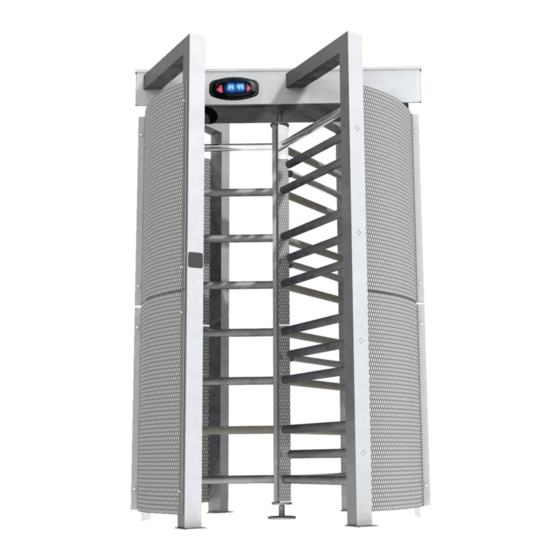
Page 5: Description Of Parts
4.3 Description of parts 1) Supporting column 2) Transom 3) Comb rotor 4) Wings with arms 5) Wings 6) Column covers 7) Safety grate 8) Transom cover 9) Mechanism 10) Control panel 11) Direction light (Stop/Go light) 1500 2250 4.4 Dimensions (mm) Single Double... -
Page 6: Preliminary Checks
5 Installing a single opening Only skilled, qualified staff must perform the installation, in full compliance of the current legislation. 5.1 Preliminary checks Before installing the automated device, please: • Set up a proper omnipolar cut-off device, with contacts more than 3 mm apart, and power source isolation; •... - Page 7 5.4 Installing the turnstile Warning: to install this at least two or three people are needed. Use hoisting equipment to move and position the turnstile When securing, the turnstile may be unstable and could tip over, so be careful not to lean onto it until securing in complete. Lay the corrugated tubes to make the connections coming from the junction pit.
- Page 8 Use the template to precisely mark the holes for securing the columns and wings. Drill the carefully marked holes using a 12 mm bit and secure the columns using appropriate 8 mm bolts. Holes for the supportino column Holes for the supportino column Holes for the lower pivot pin Holes for the wing Holes for the wing...
- Page 9 Assemble the rotor arms, join and secure the single arms to the side with bolts and to the reinforcing triangle with the washers, nuts and bolts using the issued T-driver. Finally, insert the caps using a plastic or wooden mallet and striking them on their perimeter so as not to damage them. UNI5933 M8x20 screws Reinforcing triangle UNI5587 M10 nur...
- Page 10 Insert the upper, centre swivel-pin of the rotor arms into the hole in the traverse piece, insert the Seeger ring into the swivel-pin housing and leave the rotor arms hanging from the traverse piece (suspended by the Seeger ring). Seger ring Hole Upper-centre swivel-pin Insert the dowel plugs into the holes, insert the lower pivot under the lower central disk and secure it using the bolts.
- Page 11 Secure the arms to the frames using washers and nuts. Then, insert the caps. Secure the armed frame to the centre of the traverse piece using nuts and washers. On the bottom secure it using appropriate plugs and bolts.
- Page 12 Secure the frames (without arms) to the ends of the traverse piece using nuts and washers. On the bottom use appropriate plugs and bolts. UNI1751 Washer UNI1750 Washer UNI5587 M8 Nur Bolt Dowel plug Warning! Position the cage’s upper swing-pin as shown in the drawing to allow mechanism to be inserted.
- Page 13 Position the mechanism above the upper swing-pin and secure it using nuts and washers. UNI5587 Nur UNI1751 Washer UNI1750 Washer Electromagnets Control panel housing...
- Page 14 6 Installing a double opening Only skilled, qualified staff must perform the installation, in full compliance of the current legislation. 6.1 Preliminary checks Before installing the automated device, please: • Set up a proper omnipolar cut-off device, with contacts more than 3 mm apart, and power source isolation; •...
- Page 15 6.4 Installing the turnstile Warning: to install this at least two or three people are needed. Use hoisting equipment to move and position the turnstile When securing, the turnstile may be unstable and could tip over, so be careful not to lean onto it until securing in complete. Lay the corrugated tubes to make the connections coming from the junction pit.
- Page 16 Use the template to precisely mark the holes for securing the columns and wings. Drill the carefully marked holes using a 12 mm bit and secure the columns using appropriate 8 mm bolts. Holes for the supportino column Holes for the supportino column Holes for the lower pivot pin Holes for the wing Holes for the wing...
- Page 17 Assemble the rotor arms, join and secure the single arms to the side with bolts and to the reinforcing triangle with the washers, nuts and bolts using the issued T-driver. Finally, insert the caps using a plastic or wooden mallet and striking them on their perimeter so as not to damage them. (see drawings) Note: set up the single arms to be assembled along the corresponding rotor...
- Page 18 Insert the upper, centre swivel-pin of the rotor arms into the hole in the traverse piece, insert the Seeger ring into the swivel-pin housing and leave the rotor arms hanging from the traverse piece (suspended by the Seeger ring). Hole Seger ring Upper-centre swivel-pin Insert the dowel plugs into the holes, insert the lower pivot under the lower central disk and secure it using the bolts.
- Page 19 Secure the frames (without arms) to the ends of the traverse piece using nuts and washers. On the bottom use appropriate plugs and bolts. UNI1751 Washer UNI1750 Washer UNI5587 M8 Nur Bolt Dowel plug Secure the arms to the frames using washers and nuts. Then, insert the caps.
- Page 20 Secure the frames (without arms) to the ends of the traverse piece using nuts and washers. On the bottom use appropriate plugs and bolts. UNI1751 Washer UNI1750 Washer UNI5587 M8 Nur Bolt Dowell Plug Warning! Position the cage’s upper swing-pin as shown in the drawing to allow mechanism to be inserted.
- Page 21 Position the mechanism above the upper swing-pin and secure it using nuts and washers. UNI5587 Nur UNI1751 Washer UNI1750 Washer Electromagnets Electromagnets Control panel Control panel housing housing...
-
Page 22: Electric Wiring
7 Electric wiring Position the control panel inside the traverse piece to then connect to the cables. Thread the control panel and accessories power cable along the entire height of the column through the hole all the way up the traverse piece. -
Page 23: Control Panel
7.1 Cable type and section Cable length Cable length Cable length Connection Cable type 1 < 10 m 10 < 20 m 20 < 30 m 230V power supply to control panel FROR CEI 3G x 1,5 mm 3G x 2,5 mm 3G x 4 mm 20-22 Power supply to accessories... -
Page 24: Electrical Connections
9 Electrical connections Note: the below descriptions and illustrations refer to the single turnstile, the double turnstile require doubling the electrical connections for the devices Cable gland The cables running through the electrical control panel must be secured to the proper cable holders. 9.1 Power 230V A.C. - Page 25 9.3 Connection optional devices to the control panel 24V A.C. / 500 mA power supply to accessories Panic button / (N.C. contact) Activating the contact triggers total block of the turnstile. Entrance Button or Transponder / (N.O. contact) - Activating the turnstile to enter. With a non permanent contact after 10”...
- Page 26 10 Cladding 10.1 Securing the protective grills After performing all of the electrical connections, position the protective grills between the wing-frames and the supporting columns. Note: for the single turnstile, position the grills depending on the curvature. Protective grills Single Double Protective grills UNI1751 washer...
-
Page 27: Securing The Covers
10.2 Securing the covers Once all electrical connections are complete, insert and secure the covers into the columns and transom using the bolts. Column covers Transom cover... -
Page 28: Safety Instructions
11 Safety instructions Important general safety instructions This product must be only used for its specific intended purpose. Any other use is wrongful and therefore dangerous. The manu- facturer is not liable for any harm or damage caused by improper, wrongful or unreasonable use. Danger voltage running Impact danger through parts... -
Page 29: Maintenance
(+39) 0422 4940 - fax (+39) 0422 4941 it is entirely complete and/or incorporated in compliance with what is set internet: www.came.it - e-mail: info@came.it forth by Machine Directive 98/37/CE Hereby states under its own liability, that these products to automate gates, and garage... - Page 30 (+34) 91 52 85 009 Jebel Ali Free Zone - Dubai Dubai (+34) 91 46 85 442 (+971) 4 8860046 (+971) 4 8860048 CAME United Kingdom Ltd. CAME United Kingdom Ltd. GREAT BRITAIN RUSSIA CAME Russia CAME Russia Unit 3 Orchard Business Park...
Need help?
Do you have a question about the GUARDIAN Series and is the answer not in the manual?
Questions and answers