Sign In
Upload
Manuals
Brands
NF Manuals
Amplifier
CA5351
NF CA5351 Manuals
Manuals and User Guides for NF CA5351. We have
1
NF CA5351 manual available for free PDF download: Instruction Manual
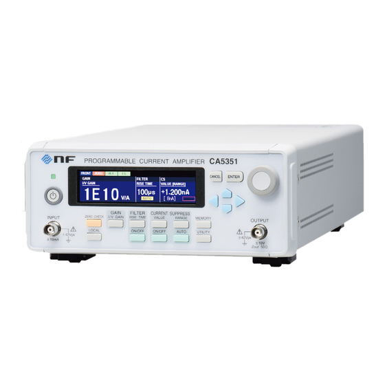
NF CA5351 Instruction Manual (151 pages)
PROGRAMMABLE CURRENT AMPLIFIER
Brand:
NF
| Category:
Amplifier
| Size: 3 MB
Table of Contents
Figures and Tables
13
Table of Contents
13
Features
16
Applications
17
List of Functions
17
Operating Principles
18
Figure 1-1 Block Diagram of the CA5351
19
2. Preparation before Use
21
Inspection
22
General Cautions
23
Installation
23
Installation Environment
23
Figure 2-1 Rack Mounting Kit Assembly Diagram (EIA for One Unit)
25
Figure 2-2 Rack Mounting Kit Assembly Diagram (EIA for Two Units)
25
Figure 2-3 Rack Mounting Kit Assembly Diagram (JIS for One Unit)
25
Figure 2-4 Rack Mounting Kit Assembly Diagram (JIS for Two Units)
25
Figure 2-5 Rack Mounting Kit Dimensions (EIA for One Unit)
25
Figure 2-6 Rack Mounting Kit Dimensions (EIA for Two Units)
25
Figure 2-7 Rack Mounting Kit Dimensions (JIS for One Unit)
25
Figure 2-8 Rack Mounting Kit Dimensions (JIS for Two Units)
25
Rack Mounting
25
Figure 2-9 Voltage Selector Switch
30
Grounding and Power Connections
30
Figure 2-10 Fuse Replacement
32
Display Check at Power on
33
Quick Operation Check
33
Self-Diagnostic Test Execution
33
Calibration
34
3. Panel Operations and Basic Operation
35
Figure 3-1 Front Panel
36
Front Panel
36
Function and Use of each Part of the Panels
36
Figure 3-2 Rear Panel
37
Rear Panel
37
Display at Power "ON
38
Display at Power "ON" and Initial Settings
38
What to Check before Turning the Power on
38
Initial Settings
39
Figure 3-3 I/O Connectors
42
I/O Connectors
42
Figure 3-4 Input Connectors
43
Figure 3-5 Output Connectors
43
Figure 3-6 Output Polarity
43
I/O Connections
44
Connection of Optical Sensor (Photodiode), Etc
45
Figure 3-7 Connection of Sensor Without Bias Type
45
Figure 3-8 Connection of Reverse Bias Type Sensor
45
Figure 3-9 Example of Connection of Photomultiplier
46
Connection to Lock-In Amplifier, Etc
47
Figure 3-10 When Signal Source Is Grounded
47
Figure 3-11 When Signal Source Cannot be Grounded
47
Operation Tree
48
Basic Operation
50
Outline of Main Screen
50
Basic Key Operation
51
Simple Operation for the First Use
55
Basic Settings
56
Figure 3-12 Input Circuit
56
Zero Check
56
Filter Settings
57
Gain Settings
57
Figure 3-13 Definition of Rise Time
59
Figure 3-14 Block Diagram of the CA5351
59
Current Suppression Settings
62
Figure 3-15 Block Diagram of the Current Suppression
64
4. Advanced Operation
65
Utilities
66
DISPLAY (Display Settings Screen)
67
INPUT (Input Select Screen)
67
RESET (Reset Execution Screen)
67
Information
68
REMOTE (Remote Control Settings Screen)
68
SELFTEST (Self-Diagnostic Test Execution Screen)
69
INITIALIZE (Initialization Execution Screen)
70
POWER on STATE (Power on State Settings Screen)
70
Memory Operation
71
CLEAR (Clear)
72
NAME (Memory Name Change)
72
RECALL (Recall)
72
STORE (Save)
72
5. Remote Control
73
Preparations before Use
74
Selection of the Remote Control Interface
74
USB Overview
74
GPIB Overview
75
LAN Overview
78
Communication Cautions
79
Switching between Remote and Local Modes
81
Responding to Interface Messages
82
List of Commands
83
List of Commands and Command Tree
83
Command Tree
84
Commands
85
Overview
85
Figure 5-1 Common Command Syntax
86
Figure 5-2 Subsystem Command Syntax
87
Figure 5-3 Numerical Parameter Syntax (<Nrf>)
88
Figure 5-4 Numerical Parameter Syntax (<NR1>)
89
Figure 5-5 Numerical Parameter Syntax (<NR2>)
89
Figure 5-6 Numerical Parameter Syntax (<NR3>)
89
Figure 5-7 Mantissa Syntax
89
Figure 5-10 Boolean Parameter Syntax (<BOL>)
90
Figure 5-8 Exponent Syntax
90
Figure 5-9 Discrete Parameter Syntax (<DISC>)
90
Figure 5-11 Text String Parameters (<STR>)
91
Figure 5-12 Block Parameter Syntax (<BLK>)
91
Figure 5-13 Suffix Syntax
92
Figure 5-14 Program Message Syntax
92
Figure 5-15 Response Message Syntax
93
Figure 5-16 Integer Response Data Syntax (<NR1>)
93
Figure 5-17 NR2 Numerical Response Data Syntax (<NR2>)
94
Figure 5-18 NR3 Numerical Response Data Syntax (<NR3>)
94
Figure 5-19 Discrete Response Data Syntax (<DISC>)
95
Figure 5-20 Numerical Boolean Response Data Syntax (<NBOL>)
95
Figure 5-21 Text String Response Data Syntax (<STR>)
95
Figure 5-22 Defined-Length Arbitrary Block Response Data Syntax (<DBLK>)
96
Sequential Commands
96
Command Details
97
Figure 5-23 Status System
105
Status System
105
Status System Overview
105
Status Byte
106
Figure 5-24 Standard Event Status Structure
107
Standard Event Status
107
Figure 5-25 Operation Status Structure
109
Operation Status
109
Error Messages
112
Commands Table Compatible with the CA5350
114
Compatibility with Commands of the CA5350
114
Detailed Description of the CA5350 Commands
117
6. Troubleshooting
125
Error Messages
126
Errors that Occur When the Instrument Power Is Turned on
127
Errors that Occur During Panel Operations
128
Errors that Occur During Operation
129
Errors that Occur During Remote Mode
129
Quick Diagnosis
131
7. Maintenance
133
Daily Maintenance
134
Introduction
134
Maintenance
134
Checking the Version Number
135
Self-Diagnostic Test
135
Storage, Repackaging, and Transport
135
Introduction
136
Performance Test
136
Current Suppression and Gain Accuracy
137
Output Offset Voltage
138
Calibration
139
Input Section
142
Current Suppression Section
143
Amplifier Section
144
Output Section
145
Miscellaneous Specifications
146
External Dimensions
148
Figure 8-1 External Dimensions of the CA5351
148
Advertisement
Advertisement
Related Products
NF CA5350
NF CA5360
NF BA4825
NF HSA4012
NF HSA4014
NF HSA4051
NF HSA4052
NF HSA42011
NF HSA42012
NF HSA42014
NF Categories
Amplifier
Measuring Instruments
AC Power Distribution
Portable Generator
Power Supply
More NF Manuals
Login
Sign In
OR
Sign in with Facebook
Sign in with Google
Upload manual
Upload from disk
Upload from URL