Table of Contents
Advertisement
Quick Links
Advertisement
Table of Contents

Summary of Contents for H Heuer Instruments UMDT51A
- Page 1 UMDT51A LINE TESTER LT51 200 Hz – 2.2 MHz Rev 9.1 April 2021 50, 75, 600 Option H HEUER INSTRUMENTS PTY LTD 766 Pennant Hills Road, Carlingford NSW 2118 Sydney, Australia Web: www.heuer.com.au Tel: +61 2 9871 8207 Fax: +61 2 9872 5985...
- Page 2 WARRANTY H Heuer Instruments Pty Ltd warrants that this product is free from defects in material and workmanship for a period of one (1) year from the date of shipment. Parts, accessories, product repairs and services are warranted for 90 days. This...
- Page 3 SAFETY WARNINGS The LT51 Line Tester has been designed to meet the requirements of IEC 61010-1:2010 (Safety Requirements for Electrical Equipment for Measurement, Control and Laboratory Use) and has been supplied in a safe condition. This User Manual contains some information and warnings which have to be followed by the user to ensure safe operation and to retain the instrument in a safe condition.
- Page 4 The following international electrical symbols may be found on the LT51 and are used in this guide: DANGER: Risk of electric shock. ATTENTION: Refer to Manual Equipment is protected by reinforced insulation to protect the user against electric shock. Functional Earth (Ground) Terminal Symbol for Waste Electrical and Electronic Equipment (WEEE) Recycling according to EU directive LT51 User Manual...
-
Page 5: Care And Maintenance
Care and Maintenance The LT51 is designed to be maintenance free. Treat it with care to ensure the best performance. The suggestions below will help you to fulfill the obligations of the warranty and enjoy the tester for many years. ... -
Page 6: Dc Power Supply
DC Power Supply An external DC power supply between 5 and 6 V supplying 1A can be connected to the LT51 for power during normal operations and to charge the NiMH Battery. The DC supply can be powered by a wall plug-pack from AC mains or an appropriately configured Car battery adaptor. -
Page 7: Supplied With The Lt51
If the LT51 is covered under warranty, it will be promptly repaired or replaced (at H Heuer Instruments option) and returned to you, postage paid, at no charge. If the warranty has lapsed, H Heuer Instruments will repair the LT51 for a fixed fee and return it, postage paid, to you. -
Page 8: Declaration Of Conformity
H Heuer Instruments Pty Ltd H HEUER INSTRUMENTS 766 Pennant Hills Road Carlingford NSW 2118 Records Australia ABN: 74 003 948 016 Declaration of Conformity Supplier’s Name: H Heuer Instruments Pty Ltd Supplier’s Address: 766 Pennant Hills Road Carlingford NSW 2118... -
Page 9: Table Of Contents
Table of Contents USER MANUAL ......................I WARRANTY ......................II SAFETY WARNINGS ..................III CARE AND MAINTENANCE ................V Battery ....................v DC Power Supply.................. vi Charging ....................vi Level of Charge ..................vi SUPPLIED WITH THE LT51 ................VII SERVICE AND ADJUSTMENT ................ VII ENVIRONMENTAL PROTECTION .............. - Page 10 Testing PLC Systems ................ 19 Measuring the Return Loss of Line Matching Units (LMU) ....23 Measuring the Blocking Impedance of Line Traps ....... 24 Configuring the Tester ..............25 LT51 Transmitter ................. 26 Output impedance ............... 26 Transmit source................26 Transmit level ................
- Page 11 Distortion (THD, S/N, S/ND, SFR) ............44 Distortion (Spectrum measurements) ..........44 Distortion (Numerical measurements) ..........47 Return Loss ..................48 Near End X-Talk (NEXT) / Loss ............49 DC / AC Voltage................... 51 Loop Current ..................52 AC Impedance (MAGZ) ............... 53 Automatic testing .................
- Page 12 Performance Testing ................. 81 Required test equipment ..............81 Transmitter Level Accuracy ..............82 Transmitter Level Response ..............82 Receiver Level Accuracy ..............83 Receiver Level Response ..............83 Return Loss Measurement Response ..........84 Return Loss Measurement ..............84 Intrinsic NEXT (Near End CossTalk) ...........
-
Page 13: Product Description
Product description 1. Product description The LT51 Line Tester is a portable handheld battery powered instrument. It combines the features of several pieces of test equipment such as a Selective Level Meter / Spectrum Analyser, Distortion Analyser, Oscillator, Handheld DMM and TDR in the one small lightweight package. - Page 14 Product description >8 hours operation with easily replaceable AA NiMH batteries Accepts commonly used 4mm banana plug test leads Choice of Graphical or Numerical measurement display Marker functions for navigating graphical displays using cursor. Remote control of LT51 by PC via serial port over opto-isolated USB link ...
-
Page 15: Controls And Connections
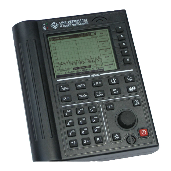
Controls and connections 2. Controls and connections LEDs Speaker Soft-keys Measurement keys Configuration keys Knob On-Off key Microphone Figure 2-1. LT51 front panel LT51 User Manual... -
Page 16: Welcome Screen
LT51 hardware, will cause the screen to hang and display an error message. Obtain the correct version of the firmware and down- load it now. Otherwise, the LT51 must be returned to H Heuer Instruments for service. -
Page 17: Lcd
Controls and connections The LT51 has a sunlight-readable, ¼-VGA (320 x 240 pixel), b&w graphic liquid crystal display. A low-power white LED array provides back-lighting to the LCD. The LCD consists of the following areas: Figure 2-3. LT51 LCD Title Bar - displays the current measurement type, RTC and battery information. -
Page 18: Keypad
Controls and connections Keypad The keypad is molded from silicone rubber and has 31 keys. The following tables describe the function of each key. Selects graphical / spectrum display mode (default: Level / Noise). Softkeys allow selection of various graphical measurements such as such as Level / Noise, Return Loss and Next / Loss. - Page 19 Controls and connections Press and hold until the LT51 turns on. Press and release to turn off. When the LT51 appears stuck on, press and hold the key until LT51 turns off (~5s). Clears currently displayed parameter entry box or message box. If no box is displayed, save the current measurement to the tester’s non volatile memory During parameter entry, moves cursor right to next digit or wraps...
-
Page 20: Test Lead Connectors
Controls and connections Test lead connectors Figure 2-4. LT51 top panel connectors The top connector panel has five 4 mm safety test lead connectors. These connectors are color-coded for easy identification. The test lead connectors are identified in Figure 2-4 as follows: ... -
Page 21: Usb Port
Controls and connections USB port The USB port on the top connector panel of the LT51 is used for down-loading new software, up-loading test results or instrument control from a PC. A standard USB cable with a type “B” plug (for the LT51) and type “A” plug for the PC is provided. -
Page 22: Battery Cover
Controls and connections Battery cover Figure 2-5. LT51 bottom panel showing battery Cover Numerical Keypad Wherever a numerical input quantity is requested (eg. TX Frequency), it is possible to set the value using the knob, or directly via the keypad. Once the first digit is entered via the keypad, a selection of units appears in the menu next to the soft-keys. -
Page 23: Testing Vf-Pcm Multiplexers
Testing VF-PCM Multiplexers 3. Testing VF-PCM Multiplexers Figure 3.1: Test Setup – VF PCM Testing with LT51 Idle Channel Noise Make the connections between the Test circuit and the LT51 as in Fig. 3.1. Turn the LT51 ON. [after Reset: Ztx = 600, Zrtx = HiZ 600, TX Source = OFF, TX Freq =10 kHz, Mode = TX-RX (4W)]. -
Page 24: Audio Level Setting
Testing VF-PCM Multiplexers Audio Level Setting Make the connections between the Test circuit and the LT51 as in Fig. 3.1. Turn the LT51 ON. [after Reset: Ztx = 600, Zrtx = HiZ 600, TX Source = OFF, TX Freq =10 kHz, Mode = TX-RX (4W)] button, then the [f2] soft-key to set Input to ‘Term’. -
Page 25: Frequency Response
Testing VF-PCM Multiplexers Frequency Response Make the connections between the Test circuit and the LT51 as in Fig. 3.1. Turn the LT51 ON. [after Reset: Ztx = 600, Zrtx = HiZ 600, TX Source = OFF, TX Freq =10 kHz, Mode = TX-RX (4W)] Press the [f5] soft-key to select the ‘NEXT Loss’... -
Page 26: Variation Of Gain With Input Level
Testing VF-PCM Multiplexers Variation of Gain with input level Make the connections between the Test circuit and the LT51 as in Fig. 3.1. Turn the LT51 ON. [after Reset: Ztx = 600, Zrtx = HiZ 600, TX Source = OFF, TX Freq =10 kHz, Mode = TX-RX (4W)] button, then the [f2] soft-key to set Input to ‘Term’. -
Page 27: Signal To Quantization Noise
Testing VF-PCM Multiplexers Signal to Quantization Noise Make the connections between the Test circuit and the LT51 as in Fig. 3.1. Turn the LT51 ON. [after Reset: Ztx = 600, Zrtx = HiZ 600, TX Source = OFF, TX Freq =10 kHz, Mode = TX-RX (4W)] button, then the [f2] soft-key to set Input to ‘Term’. -
Page 28: Cross-Talk
Testing VF-PCM Multiplexers Cross-Talk [if G.227 TEL Noise Option is fitted] Make the connections between the Test circuit and the LT51 as in Fig. 3.1. Turn the LT51 ON. [after Reset: Ztx = 600, Zrtx = HiZ 600, TX Source = OFF, TX Freq =10 kHz, Mode = TX-RX (4W)] Press the [f5] soft-key to select the ‘NEXT Loss’... -
Page 29: Ring Detect Vac / Vdc When On-Hook
Testing VF-PCM Multiplexers Ring Detect VAC / VDC when on-hook * Make the connections between the Test circuit and the LT51 as in Fig. 3.1. Turn the LT51 ON. [after Reset: Ztx = 600, Zrtx = HiZ 600, TX Source = OFF, TX Freq =10 kHz, Mode = TX-RX (4W)] Press the [f2] soft-key to select the ‘Voltage DC/AC’... -
Page 30: Vdc And Idc When Off-Hook, Level Measurement
Testing VF-PCM Multiplexers VDC and IDC when off-hook, level measurement Make the connections between the Test circuit and the LT51 as in Fig. 3.1. Turn the LT51 ON. [after Reset: Ztx = 600, Zrtx = HiZ 600, TX Source = OFF, TX Freq =10 kHz, Mode = TX-RX (4W)] Press the key to go off-hook (Loop-hold) or DC terminate (with 600) -
Page 31: Testing Plc Systems
Testing PLC Systems 4. Testing PLC Systems -40 dB Attenuator RF output 75 Ω +40 dB terminated Carrier Carrier AF/VF DATA input 600 Ω VOICE Supplied Accessory Figure 4.1: Test Setup – PLC Testing with LT51 Connect a coaxial cable between the BNC Adaptor (plugged into the LT51 RTXa-b terminals) and the RF coaxial interface of the PLC system unit. - Page 32 Testing PLC Systems Figure 4.2: Possible RF Frequency Spectrum for SSB PLC System To measure the levels of the following 3 RF frequencies: Tx Pilot at 499.820 kHz Rx Pilot at 500.180 kHz External 3.800 kHz tone at 496.200 kHz [Optional] Connect the external 3.800 kHz tone from the LT51 TXa-b terminals to the VF/AF 600 ohm input of the PLCC equipment.
- Page 33 Testing PLC Systems Adjust the span to 4.5 kHz by pressing the [f1] soft key, then turning the knob to increase or decrease the span. In spectral mode, move the marker using the knob to read the level at each frequency peak.
- Page 34 Testing PLC Systems LT51 User Manual...
-
Page 35: Measuring The Return Loss Of Line Matching Units (Lmu)
Testing PLC Systems Measuring the Return Loss of Line Matching Units (LMU) WARNING: Ensure that the LMU interface is free of all carrier signals before connecting the LT51 in RTX mode (eg. Return Loss). Permanent damage to the LT51 will result otherwise. Insert the Double Plug to BNC Adaptor into the LT51 RTXa-b terminals Connect a cable between the BNC Adaptor and the LMU coaxial interface Turn the LT51 ON.[ after reset: Ztx = 600Ω, Zrtx = HiZ 600Ω, TX Source =... -
Page 36: Measuring The Blocking Impedance Of Line Traps
Testing PLC Systems Measuring the Blocking Impedance of Line Traps Line dropper to To Disconnector overhead line in OPEN position Line Trap Overhead line must be switched off and earthed by auxiliary earth connection Figure 4.3: Test Setup – Measuring PLC Trap Impedance with LT51 Connect the RTX a-b terminals to the PLC Line Trap as shown. -
Page 37: Configuring The Tester
Configuring the Tester 5. Configuring the Tester The flexibility of the LT51 allows considerable freedom in configuring the tester for more advanced testing applications. For most applications, however, the standard configurations do not need to be modified and the automatic test suites offer a simple alternative for more repetitive testing applications. -
Page 38: Lt51 Transmitter
Configuring the Tester LT51 Transmitter The LT51 Line Tester can be configured to simultaneously transmit single or swept tones and make spectrum / DMM measurements. The transmitter can be configured in most measurement modes by pressing the key to access the settings, and its output always appears at the TXa-b terminals when ON. -
Page 39: Transmit Frequency
Configuring the Tester Press the knob or key to move the cursor to the next most significant digit to change. Turn the knob to adjust the level at this selected resolution. Repeat this process to a resolution of 0.1dB or until the desired level is obtained. -
Page 40: Sweep Step
Configuring the Tester frequency span is displayed. This is useful for recording swept measurements from an unsynchronised oscillator at the far end of a cable. Sweep Step Press the key, followed by [f2] “Meas Settings”, then [f4] “Sweep Step” to show the possible settings for the Sweep Step parameter. The Sweeping Step parameter controls the step size between successive sweep frequencies. -
Page 41: Lt51 Receiver
Configuring the Tester LT51 Receiver The LT51 Line Tester has powerful receiver measurement modes to display level/power spectrums of signals at the RTX inputs. The following settings, accessed by pressing the key, control how signals are received and adjusted for correct display on the LCD. Input Terminals All measurements are made on the RTXa-b input terminal pair. -
Page 42: Autorange
Configuring the Tester If the currently selected level range is not optimal for the signal being measured, one of the following range indicators appears on the LCD: “RNG” if the range should be reduced to measure the smaller signal. ... -
Page 43: Lt51 Frequency Bandwidth
Configuring the Tester LT51 Frequency Bandwidth Frequency span Press the key and then [f1] to select Span. Turn the knob clockwise to increase, or anti-clockwise to reduce, the Span Press the key (or any key) to clear the dialog box. ... -
Page 44: Bandwidth / Selective Level Meter
Configuring the Tester If the current display is in DMM mode, then the selective level at the current centre frequency is displayed. The Selective BW, is set to ‘25 Hz’ by default. In Spectral mode, the display is adjusted to show the centre frequency in the centre of the display and the start and stop frequencies on the axis are calculated for the currently set frequency Span. -
Page 45: Pots Connection
Configuring the Tester POTS Connection Connection to a POTS line must be made at the RTX terminals. Before making any connection ensure the tester is set to On-Hook. This will ensure that the input impedance is bridged and that no DC current will flow. In the On-Hook condition, the LT51 will respond to ring voltage by emitting an audible tone. -
Page 46: Dialling
Configuring the Tester Dialling When Off-Hook, dialling can be accomplished at any time by pressing any numeric keys including [*] & [#] from the keypad. As the DTMF digit is dialled, it is displayed on the LCD in a message box, and is also saved in the Redial buffer. -
Page 47: Marker Functions
Configuring the Tester Marker functions Press the key to access the marker functions provided in the LT51. The marker position and the corresponding value of the waveform at this position, are displayed below the graph display. Marker to peak Press the [f1] key (to Peak) to move the marker to the position of displayed waveform with the highest value at the time the key is pressed. -
Page 48: Volume Control
Configuring the Tester Volume control Any audio signal present at the RTX terminals can be monitored on the LT51 speaker. When graphical information is being displayed, the speaker volume control is accessed by depressing the knob or pressing the key. During display of DMM functions, rotating the knob will access the volume control. -
Page 49: Setting The Date And Time
Configuring the Tester Setting the date and time To set the date and time of the RTC, follow these steps: Press the key, followed by the [f3] “LT51 Settings” soft-key. To modify the date, press the [f1] “Date” soft-key. ... -
Page 51: Making Measurements
Making Measurements 6. Making measurements Measurements on the LT51 are selected by pressing the following keys: Selects graphical / spectrum display mode (default: Level / Noise). Softkeys allow selection of various graphical measurements such as such as Level / Noise, Return Loss and Next / Loss. -
Page 52: Level (Spectrum Measurements)
Making Measurements Level (Spectrum measurements) WARNING: Connection of the ‘g’ terminal to a reference ground can introduce errors when an imbalance between the ‘a’ and ‘b’ lines exists. In this case, disconnect the ‘g’ terminal from reference ground on one end of the measurement. This single-ended measurement displays the level spectrum of the signal at the RTX terminals: ... - Page 53 Making Measurements Setting the centre frequency and adjusting the frequency span, enables a portion of the frequency spectrum to be expanded (or zoomed in). The following example, where there are two tones close to 1,000 kHz illustrates this feature. Examining the spectrum from baseband with a span of 1,200 kHz, it is clear there are two peaks close to 1,000 kHz, but they cannot be resolved easily.
-
Page 54: Level (Numerical Measurements)
Making Measurements Level (Numerical measurements) To display the frequency and level in volts, of the maximum signal for the current measurement, press the key. The RMS value displayed, represents the total RMS signal level for the measurement selected across the current frequency span / BW, and the frequency displayed is that of the signal with the maximum peak. -
Page 55: Selective Level Meter
Making Measurements Selective Level Meter In DMM mode, the LT51 can make selective level measurements over its full frequency range from 200 Hz to 2.2 MHz with a BW around the centre frequency of 25 Hz, 1.74 kHz or 3.1 kHz. Selective measurements are made at the current centre frequency, by pressing key followed by the [f3] soft-key, and then choosing the BW. -
Page 56: Distortion (Thd, S/N, S/Nd, Sfr)
Making Measurements Distortion (THD, S/N, S/ND, SFR) Distortion measurements can be selected by pressing either the key, followed by the [f1] key. The measurement can be displayed in numerical format, where just the values of Level, Frequency and distortion for the input signal are displayed, or spectrum mode, where more information on the type of distortion can be determined. - Page 57 Making Measurements Press the [f3] soft-key to measure the Signal to Noise ratio, S/N. The ratio of the RMS signal amplitude to the RMS value of the sum of all other spectral components excluding all harmonics, in the current frequency span.
- Page 58 Making Measurements Press the [f5] key to measure the Spurious Free Range, SFR. The difference in dB between the RMS amplitude of the input signal and the peak spurious signal (does not have to be a harmonic). Also known as SFDR.
-
Page 59: Distortion (Numerical Measurements)
Making Measurements Distortion (Numerical measurements) To display the level, frequency and distortion of the input signal: press the key and then [f1] to measure Level/Distortion. Select the desired Distortion function by pressing the appropriate soft-key. The available distortion functions are: ... -
Page 60: Return Loss
Making Measurements Return Loss WARNING: Ensure that the interface is free of all high power signals before connecting the LT51 in RTX mode (eg. Return Loss). Permanent damage to the LT51 will result otherwise. This single-ended measurement uses an internal AC bridge circuit to measure the Return Loss of the pair connected to the RTX terminals. -
Page 61: Near End X-Talk (Next) / Loss
Making Measurements Near End X-Talk (NEXT) / Loss The noise found on local loops is caused by many sources, including light dimmers, radio signals, neon lights, electric trains and adjacent power lines, to name a few. The most common and problematic types of noise are caused by the electromagnetic coupling of signals from one local loop to another within the same cable bundle;... - Page 62 Making Measurements The following settings are relevant to Near End X-Talk measurements and should be set according to requirements: select the frequency span / centre frequency. (filter is set to NO FIL). select the impedance (always terminated). set Sweeping configuration for swept or single SINE measurements.
-
Page 63: Dc / Ac Voltage
Making Measurements DC / AC Voltage Measure the voltage between the RTXa-b terminals: press the key and then press [f2] to select Voltage, DC/AC. The DC and AC voltage between the RTXa-b terminals is continuously monitored and displayed on the LCD. The AC voltage displayed is the true RMS value of the signal detected at the selected RTX terminals. -
Page 64: Loop Current
Making Measurements Loop Current If the LT51 is configured as Off-Hook, the loop voltage measurement is made across the selected Zrtx termination and the loop current is calculated and displayed. Otherwise no loop current measurement is made. NOTE: Other equipment may use a 430 shunt to measure loop current. -
Page 65: Ac Impedance (Magz)
Making Measurements AC Impedance (MAGZ) Measure the magnitude of the AC impedance between the RTXa-b connector terminals in . The internal bridge network with a reference of 75 , is always used to measure the impedance, and provides adequate accuracy for all frequencies from 1 kHz to 500 kHz: ... -
Page 66: Automatic Testing
Making Measurements Automatic testing To enable an LT51 to act as a Master when connecting to another LT51, the Master configuration must be enabled (LT51 can always act as Slave): press the key, followed by the [f2] “Meas Settings” soft-key. ... - Page 67 Making Measurements NOTE: For a connection to be established, the remote LT51 must not be transmitting a single tone between 1.8 and 3.0 kHz, and the line attenuation at these frequencies must be less than 30dB (600 ). The local LT51 can be used to verify these conditions.
-
Page 68: Self-Test
Making Measurements Self-Test Press the key, then press [f1] to select Self-Test. NOTE: All connections to the LT51 TXab and RTXab terminals must be removed before starting the self-test. The Self-test can be performed to give the user general confidence that LT51 Hardware is functioning correctly, and that the basic calibration is still valid. - Page 69 Making Measurements press the [f3] Show Details key repeatedly to view the results of each test in the sequence. The results of each test, are automatically saved in the LT51 non-volatile memory for later up-load to a PC. Following completion of the self-test, a summary of the results are displayed, in the final column of each test.
-
Page 70: Double Ended Loss
Making Measurements Double Ended Loss This double-ended Measurement displays the loss and frequency of signals transmitted at 0 dBm from a LT51 at the far end of the pair connected to the RTX terminals: press the key and then [f2] to select Remote Loss. The following settings on the local LT51 are relevant to Doubled Ended Loss measurements and should be set according to requirements: ... -
Page 71: Far End X-Talk (Fext)
Making Measurements Far End X-Talk (FEXT) This double-ended Measurement displays the cross-talk measured at the near end of the pair connected to the RTX terminals. The far end LT51 transmits a single or swept signal over the selected frequency span at 0 dBm, on the pair connected to it’s TX terminals which is physically close to the pair connected between the RTX terminals of each LT51. -
Page 72: Tdr Measurement
Making Measurements TDR Measurement You can use the TDR Measurement to determine the length of a cable and to precisely locate faults such as Shorts, Breaks or Opens, Bridged Tap, Load Coils, Splices or Splits. During the TDR measurement, the LT51 continually applies a Pulse to the RTXa-b terminals. -
Page 73: Cable
Making Measurements In a vacuum, electricity, like light, travels at about 300,000 km/second. In cables, it travels slower than this and we refer to the speed as a % of the speed of light. This is usually expressed as the Propagation Velocity Factor or PVF. You may also see it referred to as Velocity of Propagation or VOP. -
Page 74: Pulse Width
Making Measurements Pulse width The pulse width can be quite short for short cables, but needs to be longer for greater length cables so that enough energy is introduced in the cable. If the energy is too low, there won’t be enough energy in the return wave to be detected reliably. -
Page 75: Horizontal Zoom
Making Measurements Horizontal zoom The features in the TDR display can be spread out or compressed by setting the horizontal zoom in multiples of 2: Toggle the [f4] soft-key to set Zoom to Horizontal. A dialog box appears with the text “Horizontal Zoom”. ... -
Page 76: Peak' Events
Making Measurements ‘Peak’ Events Launch pulse: The first peak on the screen is the “launch pulse” which occurs where the LT51 connects to the test leads (at a distance of 0 metres). The distance to the cursor includes the length of the test leads. Open: A clean or partial open will show up as a peak on the screen. -
Page 77: Dip' Events
Making Measurements ‘Dip’ Events Fault: A resistance fault will show as a dip on screen. The lower the value of resistance, the lower the dip. Short: A short (or 0 resistance fault) will show up as the lowest dip on the screen. -
Page 78: Saving Measurements
Making Measurements Saving measurements To save a measurement, press the key. NOTE: Pressing the key while a dialog box or status information is displayed, will not save the measurement, but clear the display. To save a short ID (max. 14 characters) with each saved measurement (or Auto- Test), the Save ID configuration must be enabled: ... -
Page 79: Recalling Saved Measurements
Making Measurements Recalling saved measurements To view a list of all the saved measurements: press the key, followed by the [f1] “Recall Tests” soft-key. A list of all the saved graphical measurements is displayed on the LCD, identified by the measurement type, it’s time/date stamp and User ID string. To display the saved text or DMM measurements, press the [f2] “Recall DMM”... -
Page 80: Recorder Mode
Making Measurements Recorder Mode When looking for intermittent faults or interference, the LT51 Recorder mode can be used to monitor a measurement over an extended period. Recordings at a specified sampling interval, are saved to internal non-volatile flash memory for later update to a PC for analysis. -
Page 81: Pc Interface
PC Interface 7. PC interface The LT51 opto-isolated USB interface can be connected with a standard USB cable, to a PC running a Windows 98, 2000, XP, Vista or 7 OS. This interface allows a user to upload stored results, control the instrument and update the LT51 firmware. -
Page 82: Lt51View Application Program
LT51View application program LT51View is a PC application program for Windows 98, 2000, XP, Vista, or 7 OS’s, developed by H Heuer Instruments Pty Ltd specifically for interfacing the PC to the LT51 Line Tester. This PC program will enable: ... -
Page 83: Controlling The Lt51
PC Interface Controlling the LT51 Control of the LT51 by a PC is possible over the USB connection, which appears as a COM port on the PC. The LT51View PC application also provides an ability to interface to the LT51 via commands read from a text file. -
Page 84: Lt51 Commands
PC Interface LT51 Commands CONFIGSETTING Syntax: <0xAD><Config><Value><xx><xx> (LT51 returns <0x99>) This command will set an internal LT51 <Config>uration to <Value>. The following Configurations and their values can be set with this command: Configuration <Config> <Value> MEASMODE 0x00 0x20 = LEVSPCTM 0x21 = PSD 0x23 = IPNOISE 0x26 = TDR... - Page 85 PC Interface LTYPE 0x09 0x00 = RTX 0x01 = TX-RX TXSOURCE 0x0A 0x00 = OFF 0x01 = ON HOOK 0x0B 0x00 = ONHOOK 0x01 = OFFHOOK 0x0C BIN#(0..239) FILTER 0x0D 0x00 = WIDE 0x01 = PSOPH 0x02 = 25 Hz 0x03 = 1.74 kHz 0x04 = 3.1 kHz GAUGE...
- Page 86 PC Interface CONFIGTXLEVEL Syntax: <0xAE><LevHi><LevLo><xx><xx> (LT51 returns <0x99>) The TX Level is set to: TxLevel = [((LevHi * 256) + LevLo – 6000) / 100] dBm Example: For TxLevel = -25.50 dBm, LevHi = 0x21, LevLo = 0x66 CONFIGTXFREQ Syntax: <0xAF><Freq1><Freq2><Freq3><Freq4> (LT51 returns <0x99>) The TX Frequency is set to: TxFreq = [(Freq1* 16,777,215) + (Freq2* 65,536) + (Freq3 * 256) + Freq4] Hz Example:...
- Page 87 PC Interface READDATA1 READDATA2 READDATA3 Syntax: READDATA1 <0xB1><xx><xx><xx><xx> Syntax: READDATA2 <0xB2><xx><xx><xx><xx> Syntax: READDATA3 <0xB3><xx><xx><xx><xx> LT51 returns: <D0><D1><D2><D3> The LT51 will return 4 bytes (signed 32-bit value with MSB D3, LSB D0) representing the data for: READDATA1 – the currently selected terminals READDATA2 –...
-
Page 88: Updating Lt51 Firmware
PC Interface Updating LT51 firmware H Heuer Instruments Pty Ltd may release new firmware for the LT51 Line Tester which can be downloaded from the H Heuer Instruments website at http://www.heuer.com.au and programmed into the LT51. Updating the firmware in the LT51 consists of the following steps: Save the new firmware file in a known location on the PC. -
Page 89: Adjustment Procedures
Adjustment procedures 8. Adjustment procedures Adjustment should be carried out at a temperature of 20C to 25C and (20 to 80) % RH Humidity. NOTE: Warm-up Time When adjusting or calibrating the LT51Transmitter, the LT51 should be configured to transmit a tone at 10 kHz, 0 dBm for a period equal to the automatic switchoff time for the LT51. -
Page 90: Tx Level
Adjustment procedures TX Level To adjust the transmitter output level of the LT51 press the [f1] Tx Level key. Press the [f1] softkey until 600 is displayed for the ZRTX and ZTX impedances. Terminate the LT51 TXa-b terminals with an external 600 load. Using a short, low capacitance cable connect the TXa-b terminals to the high impedance input of a DMM configured to measure ACV and display the measurement in dBm referenced to 600 . -
Page 91: Dc Voltage
Adjustment procedures DC Voltage To adjust the DC voltage function of the LT51 press the [f2] Volts key. Toggle the [f2] Volts key until +50 Vdc is displayed. Connect a DC Voltage Source of +50.00 V ± 0.05 % to the RTXa-b terminals with the +ve terminal to the RTXb (red) terminal. -
Page 92: Frequency (Tx And Rx Accuracy)
Adjustment procedures Frequency (TX and RX accuracy) To adjust both the Transmitter and Receiver Frequency accuracy of the LT51, press the [f3] Frequency key. Using a short, low capacitance cable connect the TXa-b terminals to the high impedance input of a DMM configured to measure Frequency to at least 8 digits (0.1 Hz resolution). -
Page 93: Performance Testing
Performance Testing 9. Performance Testing The recommended Calibration Interval is two years. Performance Testing should be performed at a temperature of 20 - 25 C and (20 to 80) % RH Humidity. The LT51 should be adjusted as specified in the Adjustment Procedure if performance testing reveals any measurement to be out of specification. -
Page 94: Transmitter Level Accuracy
Performance Testing Transmitter Level Accuracy Set the LT51 to TX-RX interface mode. Set the TX frequency to 10 kHz. Set the LT51 Ztx impedance and TX level as indicated in Table 8.1 below. Connect a suitable DMM to the LT51 using a short low capacitance cable to the TXa-b terminals. -
Page 95: Receiver Level Accuracy
Performance Testing Receiver Level Accuracy Set the LT51 to Level Spectrum and TX-RX interface mode Set the LT51 Zrtx impedance to terminated and the appropriate value in the table. Connect a Level Oscillator (with the correct level for each impedance) to the LT51 using a short low capacitance cable to the RTXa-b terminals. -
Page 96: Return Loss Measurement Response
Performance Testing Return Loss Measurement Response Set the LT51 to Return Loss mode. Set the LT51 Zrtx impedance to 75 and ensure the RTXa-b terminals are shorted together. Set the Oscillator level to -10 dBm and frequency as indicated in Table 8.5 Step down the frequencies in Table 8.5 and check that the readings are within the ranges specified. -
Page 97: Dc Voltage Measurement
Performance Testing DC Voltage Measurement Set the LT51 to DMM – AC/DC Voltage mode. Ensure that the Terminals are set to AB. Connect a 50 V DC Source to the LT51 RTXa-b terminals. Check that the LT51 displays the DC voltage as 50.0 0.5 V. Select the a-g and b-g terminals and ensure that the LT51 displays the DC voltage as 0 V. -
Page 99: Specifications
Specifications Specifications Physical Case PolyCarbonate (FV-0 rating) Display 320 x 240 Graphic LCD with LED backlight Keypad Silicone rubber with 31 keys Rotary Control 21mm knob with integrated push switch LEDs Charging, external DC power +5 C to 40 C, 20% to 80% RH Operating Temperature -20 C to 60 C Storage Temperature... -
Page 100: Sine Signal Generator (Transmitter)
Specifications Sine signal generator (transmitter) Frequency 1 Hz to 2.2 MHz (1 Hz resolution) 5 ppm 1 Hz Accuracy 600 , 75 , 50 Impedance (balanced) Level 0.1 dB resolution 200 Hz to 20 kHz up to 2.2 MHz 600 ... -
Page 101: Spectrum Analyser
Specifications Spectrum analyser Frequency range 200 Hz to 2.2 MHz 4.5, 9,18 … 600 kHz, 1.2 MHz, 2.4 MHz Frequency spans Dynamic range >60 dB (typically better than 70dB) Max displayed range 110 dB (80dB+30dB offset) Frequency resolution < 0.5% of span Distortion Fundamental Frequency range 200 Hz to 2.2 MHz... -
Page 102: Impedance Magnitude
Specifications Impedance Magnitude 200 Hz to 500 kHz (50, 75 ref) 10 to 400 ± 5% ± 5 20 kHz to 500 kHz (50, 75 ref) < 1000 ± 10% ± 5 Signalling / Voice Communication Dial Method DTMF Redial...