GEM 550 Installation, Operating, & Maintenance Instructions
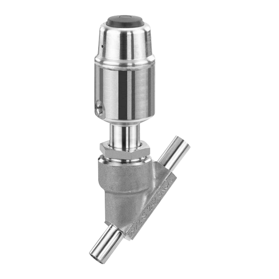
Angle seat globe valve metal, dn 6 - 80, actuator 0 and 1/2 to 5
Hide thumbs
Also See for 550:
- Installation, operating and maintenance instructions (44 pages) ,
- Assembly instructions manual (16 pages) ,
- Operating instructions manual (46 pages)
Table of Contents
Advertisement
Available languages
Available languages
Quick Links
Advertisement
Chapters
Table of Contents

Related Manuals for GEM 550


Summary of Contents for GEM 550
- Page 1 Schrägsitzventil Metall, DN 6 - 80 Angle Seat Globe Valve Metal, DN 6 - 80 ORIGINAL EINBAU- UND MONTAGEANLEITUNG INSTALLATION, OPERATING AND MAINTENANCE INSTRUCTIONS Antrieb 0 und 1 Antrieb 2 bis 5 Actuator 0 and 1 Actuator 2 to 5...
-
Page 2: Table Of Contents
Funktion des GEMÜ-Ventils: Allgemeine Sicherheitshinweise 2 Sachgerechter Transport und Lagerung Hinweise für Service- und Installation und Inbetriebnahme durch Bedienpersonal eingewiesenes Fachpersonal Warnhinweise Bedienung gemäß dieser Einbau- und Verwendete Symbole Montageanleitung Begriff sbestimmungen Ordnungsgemäße Instandhaltung Vorgesehener Einsatzbereich Auslieferungszustand Korrekte Montage, Bedienung und Wartung Technische Daten oder Reparatur gewährleisten einen... -
Page 3: Hinweise Für Service- Und
Möglicherweise gefährliche Situation! dürfen nicht ohne vorherige Abstimmung ® Bei Nichtbeachtung drohen mit dem Hersteller durchgeführt werden. Sachschäden. GEFAHR Sicherheitsdatenblätter bzw. die für die verwendeten Medien geltenden Sicherheitsvorschriften unbedingt beachten! Bei Unklarheiten: Bei nächstgelegener GEMÜ- Verkaufsniederlassung nachfragen. 3 / 44... -
Page 4: Verwendete Symbole
Vorgesehener Verwendete Symbole Einsatzbereich Gefahr durch heiße Oberflächen! Das 2/2-Wege-Ventil GEMÜ 550 ist für den Einsatz in Rohrleitungen konzipiert. Es steuert ein durchfließendes Medium Gefahr durch ätzende Stoffe! indem es durch ein Steuermedium geschlossen oder geöffnet werden kann. Das Ventil darf nur gemäß den... - Page 5 DIN ISO 228 Kv-Werte ermittelt gemäß Norm DIN EN 60534. Die Kv-Wertangaben beziehen sich auf die Steuerfunktion 1 (NC) und den größten Antrieb für die jeweilige Nennweite. Die Kv-Werte für andere Produktkonfigurationen (z. B. andere Anschlussarten oder Körperwerkstoffe) können abweichen.
- Page 6 Druck- / Temperatur-Zuordnung für Schrägsitz-Ventilkörper Zulässige Betriebsüberdrücke in bar bei Temperatur in °C* Anschluss- Werkstoff- Code Code 1, 9, 17, 37, 60, 63, 3C, 3D 25,0 23,8 21,4 18,9 17,5 16,1 0, 16, 17, 37, 59, 60, 65 25,0 24,5 22,4 20,3 18,2...
- Page 7 Antriebsgröße 2M1 Antriebsgröße 3M1 min. Steuerdruck in Abhängigkeit vom Betriebsdruck min. Steuerdruck in Abhängigkeit vom Betriebsdruck DN 50 DN 40 DN 32 DN 50 DN 25 DN 20 DN 40 DN 15 DN 32 DN 25 DN 20 Betriebsdruck [bar] Betriebsdruck [bar] Betriebsdruck [bar] Betriebsdruck [bar]...
- Page 8 Antriebsgröße 2G1 Antriebsgröße 3G1 min. Steuerdruck in Abhängigkeit vom Betriebsdruck min. Steuerdruck in Abhängigkeit vom Betriebsdruck DN 40 DN 32 DN 25 DN 50 DN 40 DN 32 DN 20 DN 25 DN 15 DN 20 Betriebsdruck [bar] Betriebsdruck [bar] Betriebsdruck [bar] Betriebsdruck [bar] Antriebsgröße 4G1...
-
Page 9: Bestelldaten
Alle Sonderausführungen nur ab Werk lieferbar Oberflächengüte nur für Ventilkörperwerkstoff C2 Ra ≤ 0,6 μm (25 μinch) für medienberührte Oberflächen, gemäß ASME BPE SF2 + SF3, innen mechanisch poliert 1903 Ra ≤ 0,8 μm (30 μinch) für medienberührte Oberflächen, gemäß DIN 11866 H3, innen mechanisch poliert 1904 Ra ≤... -
Page 10: Herstellerangaben
Bestellbeispiel Nennweite Gehäuseform (Code) Anschlussart (Code) Ventilkörperwerkstoff (Code) Sitzdichtung (Code) Steuerfunktion (Code) Antriebsgröße (Code) Durchflussrichtung (Code) Federsatz (Code) Ausführungsart (Code) Ausführung für den Kontakt mit Lebensmitteln Für den Kontakt mit Lebensmitteln muss das Produkt mit folgenden Bestelloptionen bestellt werden: Sitzdichtung Code 5, 5G Ventilkörperwerkstoff Code 34, 37, 40, C2 Herstellerangaben Lagerung... -
Page 11: Funktionsbeschreibung
Funktionsbeschreibung Geräteaufbau Das fremdgesteuerte 2/2 Wege-Ventil Optische GEMÜ 550 ist ein Metall-Schrägsitzventil Stellungsanzeige mit Durchgangskörper und besitzt einen Kolbenantrieb. Die Ventilkörper sind gemäß Datenblatt in verschiedenen Ausführungen erhältlich. Das Ventil hat bei Steuerfunktion NC serienmäßig eine optische Steuermedium- Stellungsanzeige (für Steuerfunktion anschluss NO und DA auf Anfrage). -
Page 12: Montage Und Anschluss
Teller Maximal zulässigen Druck nicht überschreiten! ® Eventuell auftretende Druckstöße (Wasserschläge) durch Schutzmaßnahmen vermeiden. Montagearbeiten nur durch geschultes Fachpersonal. Geeignete Schutzausrüstung gemäß Eckkörper Eckkörper den Regelungen des Anlagenbetreibers gegen den Teller mit dem Teller berücksichtigen. 12 / 44... - Page 13 Montage: Montage bei Flanschanschluss: 1. Eignung des Ventils für jeweiligen Ventil im angelieferten Zustand einbauen: Einsatzfall sicherstellen. Das Ventil 1. Auf saubere und unbeschädigte muss für die Betriebsbedingungen Dichtflächen der Anschlussflansche des Rohrleitungssystems (Medium, achten. Mediumskonzentration, Temperatur 2. Flansche vor Verschrauben sorgfältig und Druck) sowie die jeweiligen ausrichten.
-
Page 14: Bedienung
11.2 Bedienung 11.3 Steuerfunktionen Optische Stellungsanzeige Folgende Steuerfunktionen sind verfügbar: Steuerfunktion 1 Federkraft geschlossen (NC): Ruhezustand des Ventils: durch Federkraft geschlossen. Ansteuern des Antriebs (Anschluss 2) öffnet das Ventil. Entlüften des Ventil off en Ventil geschlossen Antriebs bewirkt das Schließen des Ventils durch Federkraft. -
Page 15: Steuermedium Anschließen
Gewinde der Steuermediumanschlüsse 2 Verschmutzungen reinigen (Teile und 4: dabei nicht beschädigen). Teile auf Beschädigung prüfen, ggf. Antriebsgröße Gewinde auswechseln (nur Originalteile von GEMÜ verwenden). 1, 2 G 1/8 12.2 Auswechseln der Dichtungen 3, 4, 5 G 1/4 Wichtig: Steuerfunktion Anschlüsse... -
Page 16: Montage Antrieb
4. Alle Teile reinigen, dabei nicht zerkratzen 1. Antrieb A in Offen-Position bringen. oder beschädigen. 2. Antrieb 360° drehbar. Position der 5. Neue Sitzdichtung 14 einlegen. Steuermediumanschlüsse beliebig. 6. Scheibe e einlegen. 3. Gewinde der Überwurfmutter a mit 7. Geeignetes Schraubensicherungsmittel geeignetem Schmiermittel fetten. -
Page 17: Inspektion Und Wartung
Für Schäden welche durch unsachgemäße Handhabung oder Fremdeinwirkung entstehen, übernimmt GEMÜ keinerlei Haftung. Nehmen Sie im Zweifelsfall vor Inbetriebnahme Kontakt mit GEMÜ auf. 1. Geeignete Schutzausrüstung gemäß den Regelungen des Anlagenbetreibers berücksichtigen. 2. Anlage bzw. Anlagenteil stilllegen. 3. Gegen Wiedereinschalten sichern. -
Page 18: Demontage
(siehe Kapitel 11.4 Hinweis zur Richtlinie 2014/34/EU "Steuermedium anschließen"). (ATEX Richtlinie): Ein Beiblatt zur Richtlinie 2014/34/ EU liegt dem Produkt bei, sofern es Entsorgung gemäß ATEX bestellt wurde. Alle Ventilteile Hinweis zur entsprechend den Mitarbeiterschulung: Entsorgungsvorschriften / Zur Mitarbeiterschulung nehmen Umweltschutzbestimmungen Sie bitte über die Adresse auf der... -
Page 19: Fehlersuche / Störungsbehebung
Spindelabdichtung undicht aus Leckagebohrung* Verschmutzungen untersuchen Betriebsmedium entweicht Stopfbuchspackung defekt Antrieb austauschen aus Leckagebohrung* Steuerdruck gemäß Datenblatt einstellen. Steuerdruck zu niedrig Vorsteuerventil prüfen und ggf. austauschen Steuermedium nicht angeschlossen Steuermedium anschließen Ventil öffnet nicht bzw. nicht Steuerkolben bzw. Antrieb austauschen und Steuermedium auf vollständig... -
Page 20: Schnittbild Und Ersatzteile
Schnittbild und Ersatzteile Entlüftungsbohrung Anschluss 4 Anschluss 2 Leckagebohrung Pos. Benennung Bestellbezeichnung Ventilkörper K 500... Dichtring 550...SVS... Sitzdichtung Antrieb 9550 Überwurfmutter Spindel Ventilteller Mutter / Tellerscheibe / Regelkegel Scheibe 20 / 44... -
Page 21: Einbauerklärung
4.1.2.6. b); 4.1.2.6. c); 4.1.2.6. d); 4.1.2.6. e); 4.1.3.; 4.2.1.; 4.2.1.4.; 4.2.2.; 4.2.3.; 4.3.1.; 4.3.2.; 4.3.3.; 4.4.1.; 4.4.2.; 5.3.; 5.4.; 6.1.1.; 6.3.3.; 6.4.1.; 6.4.3. Ferner wird erklärt, dass die speziellen technischen Unterlagen gemäß Anhang VII Teil B erstellt wurden. Es wird ausdrücklich erklärt, dass die unvollständige Maschine allen einschlägigen... -
Page 22: Eu-Konformitätserklärung
Konformitätsbewertungsverfahren: Modul H Hinweis für Armaturen mit einer Nennweite ≤ DN 25: Die Produkte dürfen gemäß Artikel 4, Absatz 3 der Druckgeräterichtlinie 2014/68/EU keine CE- Kennzeichnung tragen. Die Produkte werden entwickelt und produziert nach GEMÜ eigenen Verfahrensanweisungen und Qualitätsstandards, welche die Forderungen der ISO 9001 und der ISO 14001 erfüllen. - Page 23 Contents General information Prerequisites to ensure that the GEMÜ valve General information functions correctly: General safety information Correct transport and storage Information for service Installation and commissioning by trained and operating personnel personnel Warning notes Operation according to these installation,...
-
Page 24: Information For Service And Operating Personnel
® Non-observance can cause damage to be performed without consulting the property. manufacturer first. DANGER Strictly observe the safety data sheets or the safety regulations that are valid for the media used. In cases of uncertainty: Consult the nearest GEMÜ sales office. 24 / 44... -
Page 25: Symbols Used
Condition as supplied to customer Control function The possible actuation functions of the The GEMÜ valve is supplied as a separately valve. packed component. Technical data Versions 0K, 1K, 2K, 3L and 4L are only valid for connection code 80 in combination with valve body material C2 (only DN 15, 20, 25, 40, 50 and 65). - Page 26 Maximum permissible seat leakage class / Control valve Seat seal Standard Test procedure Leakage rate Test medium PTFE DIN EN 60534-4 Control pressure [bar] C. f. 1 Normally closed (NC) / Flow direction: under the seat Actuator size 1G1, 1K1, 2G1, 2K1, 3G1, 3K1, 4G1, 4K1 4 - 8 0G1, 5G1, 5K1 5 - 8...
- Page 27 Pressure / temperature correlation for angle seat globe valve bodies Max. allowable operating pressures in bar at temperature °C* Connection Material code code 1, 9, 17, 37, 60, 63, 3C, 3D 25.0 23.8 21.4 18.9 17.5 16.1 0, 16, 17, 37, 59, 60, 65 25.0 24.5 22.4...
- Page 28 Actuator size 2M1 Actuator size 3M1 Min. control pressure dependent on operating pressure Min. control pressure dependent on operating pressure DN 50 DN 40 DN 32 DN 50 DN 25 DN 20 DN 40 DN 15 DN 32 DN 25 DN 20 Operating pressure [bar] Operating pressure [bar]...
- Page 29 Actuator size 2G1 Actuator size 3G1 Min. control pressure dependent on operating pressure Min. control pressure dependent on operating pressure DN 40 DN 32 DN 25 DN 50 DN 40 DN 32 DN 20 DN 25 DN 15 DN 20 Betriebsdruck [bar] Betriebsdruck [bar] Betriebsdruck [bar]...
-
Page 30: Order Data
Order data Versions 0K, 1K, 2K, 3L and 4L are only valid for connection code 80 in combination with valve body material C2 (only DN 15, 20, 25, 40, 50 and 65). Control function Code Body configuration Code 2/2-way body Normally closed (NC) Angle body... - Page 31 Version Code Media temperature -10 to 210 °C 2023 (only with seat seal Code 5G and 10) Special bleed system in the actuator 6996 All special versions only available ex works Surface finish for valve body material C2 Ra ≤ 0.6 μm (25 μinch) for process contact surfaces, in accordance with ASME BPE SF2 + SF3, mechanically polished internal 1903 Ra ≤...
-
Page 32: Manufacturer's Information
Manufacturer’s information Functional description The GEMÜ 550 pneumatically operated 2/2- Transport way valve is a metal angle seat globe valve with a straight through body and a piston Only transport the valve by suitable actuator. The valve bodies are available in means. -
Page 33: Construction
The month of manufacture is encoded in permissible pressure! the traceability number and can be obtained ® Take precautionary measures to from GEMÜ. avoid possible pressure surges The product was manufactured in Germany. (water hammer). Installation work must only be performed by trained personnel. - Page 34 Installation location: Installation: 1. Ensure the suitability of the valve for CAUTION each respective use. The valve must be appropriate for the piping system Do not apply external force to the valve. operating conditions (medium, medium Choose the installation location so that concentration, temperature and the valve cannot be used as a foothold pressure) and the prevailing ambient...
-
Page 35: Operation
11.3 Control functions Installation - Flange connection: Install the valve in the condition it is The following control functions are available: delivered in: 1. Pay attention to clean, undamaged sealing Control function 1 surfaces on the mating flanges. Normally closed (NC): 2. -
Page 36: Connecting The Control Medium
After disassembly, clean all parts of contamination (do not damage Actuator size Thread parts). Check parts for potential damage, replace if necessary (only use genuine parts from GEMÜ). 1, 2 G 1/8 3, 4, 5 G 1/4 36 / 44... -
Page 37: Replacement Of Seals
12.2 Replacement of seals Product label of Valve body marking actuator Important: RAxxx R002 Replace gasket 4 during every RBxxx R004 actuator disassembly / assembly. RCxxx R006 1. Disassemble actuator A as described in RDxxx R008 chapter 12.1, points 1-4. RExxx R010 2. -
Page 38: Commissioning
(water hammer). by improper handling or third-party actions. Prior to cleaning or commissioning the In case of doubt, contact GEMÜ before plant: commissioning. Check the tightness and the function of the valve (close and reopen the valve). -
Page 39: Disassembly
Clean the valve. Request a goods return declaration form from GEMÜ. Returns must be made with a completed declaration of return. If not completed, GEMÜ cannot process credits or repair work but will dispose of the goods at the operator's expense. -
Page 40: Troubleshooting / Fault Clearance
Troubleshooting / Fault clearance Fault Possible cause Fault clearance Control medium escapes from vent hole* in the Replace actuator and check control medium actuator cover (for control Control piston leaky for impurities function NO) or connector 2* (for control function NC) Control medium escapes Replace actuator and check control medium Spindle seal leaking... -
Page 41: Sectional Drawing And Spare Parts
Sectional drawing and spare parts Vent hole Connector 4 Connector 2 Leak detection hole Item Name Order description Valve body K 500... Gasket 550...SVS... Seat seal Actuator 9550 Union nut Spindle Valve plug Nut / retaining washer / regulating cone Washer 41 / 44... -
Page 42: Declaration Of Incorporation
Declaration of Incorporation according to the EC Machinery Directive 2006/42/EC, Annex II, 1.B for partly completed machinery Manufacturer: GEMÜ Gebr. Müller Apparatebau GmbH & Co. KG Postfach 30 Fritz-Müller-Straße 6-8 D-74653 Ingelfingen-Criesbach Description and identification of the partly completed machinery: Make: GEMÜ... -
Page 43: Eu Declaration Of Conformity
According to section 4, paragraph 3 of the Pressure Equipment Directive 2014/68/EU these products must not be identified by a CE-label. The products are developed and produced according to GEMÜ process instructions and quality standards which comply with the requirements of ISO 9001 and of ISO 14001. - Page 44 GEMÜ Gebr. Müller Apparatebau GmbH & Co. KG · Fritz-Müller-Str. 6-8 · D-74653 Ingelfi ngen-Criesbach Telefon +49(0)7940/123-0 · Telefax +49(0)7940/123-192 · info@gemue.de · www.gemu-group.com...
Need help?
Do you have a question about the 550 and is the answer not in the manual?
Questions and answers