Chapters
Table of Contents

Related Manuals for GEM 565


Summary of Contents for GEM 565
- Page 1 Regelventil Kunststoff / Metall, DN 3 - 15 Control Valve Plastic / Metal, DN 3 - 15 ORIGINAL EINBAU- UND MONTAGEANLEITUNG INSTALLATION, OPERATING AND MAINTENANCE INSTRUCTIONS...
-
Page 2: Table Of Contents
Funktion des GEMÜ-Ventils: Allgemeine Sicherheitshinweise 2 Sachgerechter Transport und Lagerung. Hinweise für Service- Installation und Inbetriebnahme durch und Bedienpersonal eingewiesenes Fachpersonal. Warnhinweise Bedienung gemäß dieser Einbau- und Verwendete Symbole Montageanleitung. Begriff sbestimmungen Ordnungsgemäße Instandhaltung. Vorgesehener Einsatzbereich Auslieferungszustand Korrekte Montage, Bedienung und Wartung Technische Daten oder Reparatur gewährleisten einen... -
Page 3: Hinweise Für Service
Möglicherweise gefährliche Situation! Nur entsprechend der Leistungsdaten ® Bei Nichtbeachtung drohen mittlere bis betreiben. leichte Verletzungen. Wartungsarbeiten und Reparaturen VORSICHT (OHNE SYMBOL) dürfen nur durch GEMÜ vorgenommen werden. Möglicherweise gefährliche Situation! GEFAHR ® Bei Nichtbeachtung drohen Sachschäden. Sicherheitsdatenblätter bzw. die für... -
Page 4: Verwendete Symbole
Es steuert ein durchfl ießendes Medium indem es durch ein Steuermedium geschlossen oder Hand: Beschreibt allgemeine geöff net werden kann. Hinweise und Empfehlungen. Das Ventil darf nur gemäß den technischen Daten eingesetzt werden Punkt: Beschreibt auszuführende (siehe Kapitel 6 "Technische Daten"). Tätigkeiten. WARNUNG Pfeil: Beschreibt Reaktion(en) auf ®... -
Page 5: Technische Daten
Technische Daten Betriebsmedium Steuermedium Aggressive, neutrale, gasförmige und flüssige Medien, die Neutrale Gase die physikalischen und chemischen Eigenschaften des Max. zul. Temperatur des Steuermediums 70 °C jeweiligen Gehäuse- und Dichtwerkstoffes nicht negativ beeinflussen. Füllvolumen: Antriebsgröße 1T2 0,031 dm³ Medientemperatur: Ventilgehäuse Kunststoff: siehe Tabelle unten Antriebsgröße 1T3 0,031 dm³... - Page 6 Kvs-Werte [l/h] Kurven DN 3 (Sitz) Kurven DN 6 (Sitz) Kurve Kvs-Wert [l/h] Kurve Kvs-Wert [l/h] Hub [mm] Hub [mm] Kurven DN 10 (Sitz) Kurven DN 15 (Sitz) Kurve Kvs-Wert [l/h] Kurve Kvs-Wert [l/h] 1000 2500 1600 3300 1600 3300 Hub [mm] Hub [mm] 6 / 32...
-
Page 7: Bestelldaten
Kvs-Wert Um ein komplettes Regelventil zu konfigurieren, muss das pneumatisch betätigte Basisventil mit einem elektropneumatischen Regler kombiniert werden. Dazu stehen die Stellungs- und Prozessregler GEMÜ 1434, 1435 und 1436 zur Verfügung. Unten finden Sie zwei Konfigurationsbeispiele für ein komplettes Ventil. -
Page 8: Herstellerangaben
Stellungs- oder Prozessregler betrieben Verpackungsmaterial entsprechend werden. Der direkte oder externe Anbau den Entsorgungsvorschriften / eines Reglers (GEMÜ 1434, 1435, 1436) ist Umweltschutzbestimmungen entsorgen. erforderlich. Geräteaufbau Lieferung und Leistung Ware unverzüglich bei Erhalt auf Vollständigkeit und Unversehrtheit... -
Page 9: Montage Und Anschluss
Schutzmaßnahmen vermeiden. schalten. Montagearbeiten nur durch geschultes 5. Anlage bzw. Anlagenteil vollständig Fachpersonal. entleeren und abkühlen lassen bis Geeignete Schutzausrüstung gemäß Verdampfungstemperatur des Mediums den Regelungen des Anlagenbetreibers unterschritten ist und Verbrühungen berücksichtigen. ausgeschlossen sind. 6. Anlage bzw. Anlagenteil fachgerecht dekontaminieren, spülen und belüften. -
Page 10: Steuerfunktion
(Steuermediumanschluss) öffnet das vorgenommen noch Ersatzteile Ventil. Entlüften des Antriebs bewirkt das ausgetauscht. Schließen des Ventils durch Federkraft. GEMÜ 565 kann nur im Hause GEMÜ repariert werden. Auch der Austausch von Ersatzteilen darf nur durch GEMÜ vorgenommen werden. Bei Nichtbeachten dieser... -
Page 11: Inbetriebnahme
Vor Inbetriebnahme Dichtheit Fremdeinwirkung entstehen, übernimmt der Medienanschlüsse GEMÜ keinerlei Haftung. prüfen! Nehmen Sie im Zweifelsfall vor Dichtheitsprüfung Inbetriebnahme Kontakt mit GEMÜ auf. nur mit geeigneter Schutzausrüstung. 1. Geeignete Schutzausrüstung gemäß den Regelungen des Anlagenbetreibers VORSICHT berücksichtigen. Gegen Leckage vorbeugen! 2. -
Page 12: Demontage
Vorsichtsmaßnahmen wie die Montage. (ATEX Richtlinie): Das komplette Ventil mit geeigneten Ein Beiblatt zur Richtlinie 2014/34/ Mitteln aus der Anlage ausbauen. EU liegt dem Produkt bei, sofern es gemäß ATEX bestellt wurde. Entsorgung Hinweis zur Mitarbeiterschulung: Alle Ventilteile Zur Mitarbeiterschulung nehmen entsprechend den Sie bitte über die Adresse auf der... -
Page 13: Fehlersuche / Störungsbehebung
Fehler Möglicher Grund Fehlerbehebung Steuermedium entweicht Steuermedium auf Verschmutzungen untersuchen, aus Entlüftungs- und Antrieb* defekt ggf. Ventil zur Reparatur an GEMÜ senden Leckagebohrungen* Betriebsmedium entweicht aus Entlüftungs- und Trennmembrane* defekt Ventil zur Reparatur an GEMÜ senden Leckagebohrungen* Steuerdruck zu niedrig Steuerdruck gemäß... -
Page 14: Schnittbild
Schnittbild Weggeber für den externen Anbau von Stellungs- oder Prozessreglern Antrieb Steuermediumanschluss Entlüftungs- und Entlüftungs- und Leckagebohrung Leckagebohrung Überwurfmutter Ansatz für Ansatz für Hakenschlüssel Hakenschlüssel mit Zapfen mit Zapfen Trennmembrane Regelkegel Ventilkörper 14 / 32... -
Page 15: Ersatzteile
Ersatzteile 3. Ventilkörper 4 entfernen. Position Bezeichnung Antrieb Trennmembrane 21.1 Austausch Trennmembrane 4. Regelkegel 5, Trennmembrane 2 und Scheibe 6 aus Ventil demontieren. 5. Teile auf Beschädigung überprüfen. 6. Trennmembrane 2 austauschen. 7. Teile in umgekehrter Reihenfolge 1. Antrieb A in Position offen fahren. wieder montieren (Dabei Regelkegel 5, Trennmembrane 2 und Scheibe 6 handfest anziehen). -
Page 16: Einbauerklärung
4.1.2.6. c); 4.1.2.6. d); 4.1.2.6. e); 4.1.3.; 4.2.1.; 4.2.1.4.; 4.2.2.; 4.2.3.; 4.3.1.; 4.3.2.; 4.3.3.; 4.4.1.; 4.4.2.; 5.3.; 5.4.; 6.1.1.; 6.3.3.; 6.4.1.; 6.4.3. Ferner wird erklärt, dass die speziellen technischen Unterlagen gemäß Anhang VII Teil B erstellt wurden. Es wird ausdrücklich erklärt, dass die unvollständige Maschine allen einschlägigen Bestimmungen der folgenden EG-Richtlinien entspricht: 2006/42/EC:2006-05-17: (Maschinenrichtlinie) Richtlinie 2006/42/EG des Europäischen Parlaments und... - Page 17 Contents General notes Prerequisites for the correct function of the General notes GEMÜ valve: General safety notes Correct transport and storage. Information for service and operating Installation and commissioning by trained personnel personnel. Warning notes Operation according to these installation, Symbols used operating and maintenance instructions.
-
Page 18: Information For Service And Operating Personnel
fi rst. DANGER Strictly observe the safety data sheets or the safety regulations that are valid for the media used. In cases of uncertainty: Consult the nearest GEMÜ sales offi ce. 18 / 32... -
Page 19: Symbols Used
The medium whose increasing or decreasing pressure causes the valve to be actuated and operated. Condition as supplied to Control function customer The possible actuation functions of the The GEMÜ valve is supplied as a separately valve. packed component. 19 / 32... -
Page 20: Technical Data
Technical data Working medium Control medium Corrosive, inert, gaseous and liquid media which have no Inert gases negative impact on the physical and chemical properties of Max. perm. temperature of control medium 70 °C the body and seal material. Filling volume: Media temperature: Plastic valve body: see table below... - Page 21 Kvs values [l/h] Characteristics DN 3 (seat) Characteristics DN 6 (seat) Characteristic Kvs value [l/h] Characteristic Kvs value [l/h] Stroke [mm] Stroke [mm] Characteristics DN 10 (seat) Characteristics DN 15 (seat) Characteristic Kvs value [l/h] Characteristic Kvs value [l/h] 1000 2500 1600 3300...
-
Page 22: Order Data
In order to configure a complete control valve the pneumatically operated basic valve must be paired with an electro-pneumatic positioner. The GEMÜ 1434, 1435 and 1436 positioners and process controllers can be used for this purpose. You will find below two configuration examples of a complete valve. -
Page 23: Manufacturer's Information
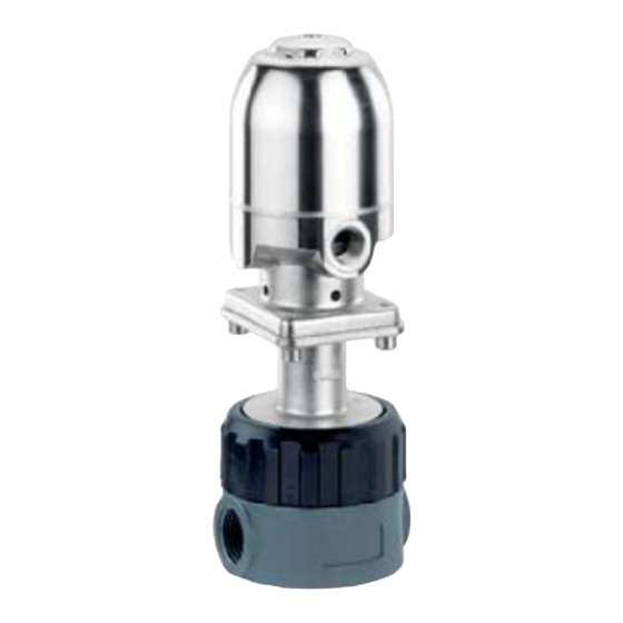
Functional description Item number Serial number The month of manufacture is encoded in The GEMÜ 565 2/2-way control valve has a the traceability number and can be obtained stainless steel piston actuator. All metallic from GEMÜ. actuator components are made of stainless The product was manufactured in Germany. -
Page 24: Installation And Connection
Installation and connection Installation location: CAUTION Prior to installation: Ensure that valve body and isolating Do not apply external force to the valve. diaphragm material are appropriate Choose the installation location so that and compatible to handle the working the valve cannot be used as a foothold. medium. -
Page 25: Control Function 1
GEMÜ 565 can only be repaired by GEMÜ. The replacement of spare parts may only be carried out by GEMÜ. If this procedure is not observed, the purchaser's guarantee rights and the manufacturer's legal liability cease. -
Page 26: Commissioning
Check the tightness of the by improper handling or third-party media connections prior to actions. commissioning! In case of doubt, contact GEMÜ before Use only the appropriate commissioning. protective gear when performing the tightness 1. Use appropriate protective gear as specifi ed check. -
Page 27: Disassembly
Clean the valve. Request a goods return declaration form from GEMÜ. Returns must be made with a completed declaration of return. If not completed, GEMÜ cannot process credits or repair work but will dispose of the goods at the operator's expense. -
Page 28: Troubleshooting / Fault Clearance
Control pressure too low Set control pressure in accordance with data sheet Control medium not connected Connect control medium Valve doesn't open or Send valve to GEMÜ for repair and check control Actuator* faulty doesn't open fully medium for impurities Positioner faulty... -
Page 29: Sectional Drawing
Sectional drawing Travel sensor for remote mounting of positioners or process controllers Actuator Control medium connector Vent hole and leak Vent hole and leak detection hole detection hole Union nut Attachment Attachment for pin wrench for pin wrench Isolating diaphragm Regulating cone Valve body 29 / 32... -
Page 30: Spare Parts
Spare parts 3. Remove valve body 4. Item Designation Actuator Isolating diaphragm 21.1 Replacing the isolating diaphragm 4. Dismantle regulating cone 5 , isolating diaphragm 2 and washer 6 from the valve. 5. Check parts for potential damage. 6. Replace isolating diaphragm 2. 7. -
Page 31: Declaration Of Incorporation
Declaration of Incorporation according to the EC Machinery Directive 2006/42/EC, Annex II, 1.B for partly completed machinery Manufacturer: GEMÜ Gebr. Müller Apparatebau GmbH & Co. KG Postfach 30 Fritz-Müller-Straße 6-8 D-74653 Ingelfingen-Criesbach Description and identification of the partly completed machinery: Make: GEMÜ... - Page 32 GEMÜ Gebr. Müller Apparatebau GmbH & Co. KG · Fritz-Müller-Str. 6-8 · D-74653 Ingelfi ngen-Criesbach Telefon +49(0)7940/123-0 · Telefax +49(0)7940/123-192 · info@gemue.de · www.gemu-group.com...
Need help?
Do you have a question about the 565 and is the answer not in the manual?
Questions and answers