Advertisement
Quick Links
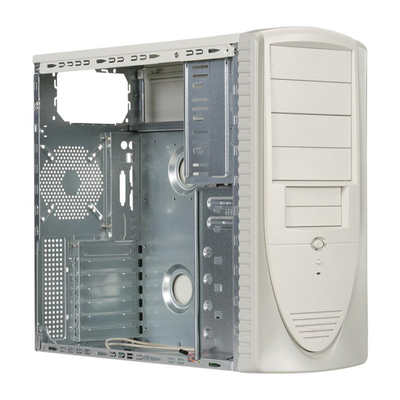
ATXB1KL Series Installation Guide
1:Unscrew the Thrum Screws
from Side Panel.
4:Put the motherboard Stand-Offs 5.Sit the motherboard on the
on the Motherboard Tray.
7.Screw in all the screws into the
Motherboard Stand-Offs
2.Pull the Side Panel back then
pull out.
Motherboard Tray.
8.Same as Step 7.
3:Find the motherboard Stand-Offs
From the enclosed Screw Box.
6.Find screws in the Screw Box.
Advertisement

Related Manuals for Apevia ATXB1KL Series


Summary of Contents for Apevia ATXB1KL Series
- Page 1 ATXB1KL Series Installation Guide 1:Unscrew the Thrum Screws from Side Panel. 4:Put the motherboard Stand-Offs 5.Sit the motherboard on the on the Motherboard Tray. 7.Screw in all the screws into the Motherboard Stand-Offs 2.Pull the Side Panel back then pull out. Motherboard Tray.
- Page 2 9.Take out front panel:(Optional. Only if you want to install case fans in the front) Step (1): Unscrew the side panel panel motherboard side. Step (4): Unscrew the other 3 screws from the other side. 10.Optional: Install Case Fan at rear (1*80mm-120mm fan) Step (2): Take out the side panel (motherboard side)
- Page 3 13.Secure the 5.25” drives with screws. 16.Install 3.5” hidden drives such as Hard Drive, Zip Drive. 19.Plug into your motherboard. Different M/B has different Layout. Please refer to M/B user’s manual. 14.Push out the 3.5” metal plate from inside.(You may use screw drive to force it out) 17.Screw all 3.5”...
- Page 4 22.Find 2*USB Cables. (USB1 & USB2) 25.Plug them onto your M/B. Please refer to M/B User’s Manual. “-P LED” cables and plug onto M/B. Screw Box. 28.Install Case Speaker to M/B following M/B User’s Manual. 23.Plug USB Cables to your M/B. Please refer to M/B User’s Manual.
- Page 5 31.Put the I/O slot back. 32.Screw the I/O slot back. 33.Find “Case Feet” in Screw Box. Lay case down and snap “Case Feet” on.
Need help?
Do you have a question about the ATXB1KL Series and is the answer not in the manual?
Questions and answers