Advertisement
Quick Links
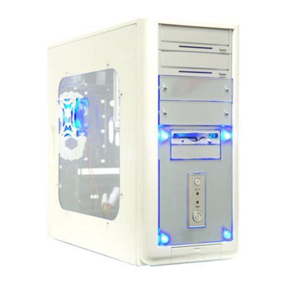
ATXB5KLW(X-Gear) Series Installation Guide
1:Unscrew the thumb screws
from side panel.
4:Put the motherboard stand-offs 5.Sit the motherboard on the
on the motherboard tray.
7.Screw in all the screws into the
motherboard stand-offs
2.Pull the side panel back then
pull out.
motherboard tray.
8.Same as Step 7.
3:Find the motherboard stand-offs
from the enclosed screw box.
6.Find screws in the screw box.
Advertisement

Related Manuals for Apevia X-Gear ATXB5KLW Series


Summary of Contents for Apevia X-Gear ATXB5KLW Series
- Page 1 ATXB5KLW(X-Gear) Series Installation Guide 1:Unscrew the thumb screws from side panel. 4:Put the motherboard stand-offs 5.Sit the motherboard on the on the motherboard tray. 7.Screw in all the screws into the motherboard stand-offs 2.Pull the side panel back then pull out. motherboard tray.
- Page 2 9.Take out front panel: Step (1): Unscrew the side panel panel (motherboard side) Step (4): Unscrew the other 2 screws from the other side. 10.Optional:Install case fan in the front panel (You can put up to 2*80mm fans in the front.) Step (2): Take out the side panel (motherboard side) Step (5): Pull out the front panel...
- Page 3 13.Secure the 5.25” drives in place with screws. 16.Screw all 3.5” hidden drives with screws. 19.Find the audio cables and bring them through the I/O slot to outside of the back panel. 14.Slide in 3.5” floppy drive and secure with screws. 17.Snap in the front panel and screw the front panel to the case.
- Page 4 22.Find the 4pin connectors (Female and Male) from case fan. Connect the Male to the female 4pin from power supply. 25.Find the 4-pin P4 connector from power supply.(for P4 only) 28.Plug USB cables to your M/B. Please refer to M/B user manual. 23.Find the 20-pin connector from power supply.
- Page 5 31.Find “Power SW” and “+P LED” “-P LED” cables and plug onto M/B. Please refer to M/B user manual. 34.Install case speaker to M/B following M/B user manual. 37.Once power on, the front 4 LEDs will light up. Note: You can link together all the 4-pin connectors(male to female) from all the case fans, LED, HDD and just use one of the 4-pin Molex connectors from power supply.
Need help?
Do you have a question about the X-Gear ATXB5KLW Series and is the answer not in the manual?
Questions and answers