Advertisement
Advertisement

Related Manuals for Apevia X-Qpack2


Summary of Contents for Apevia X-Qpack2
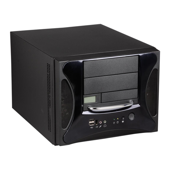
- Page 1 USER'S MANUAL...
-
Page 2: Table Of Contents
1. Install motherboard, 3 1/2", and 5 1/4" drives...1 2. Identify the power supply connectors...6 3. Install front panel leads and LEDs...7 4. Install Hard Drive and CPU temperature sensors...7 5. USB/1394(Firewire)/Audio cable pin assignment...8 6. Complete the Installation...9 CONTENTS... -
Page 3: Install Motherboard, 3 1/2", And 5 1/4" Drives
All screws for M/B, DVD, HDD are provided inside of the chassis. 1. Install motherboard, 3 1/2", and 5 1/4" drives: 1.1 Remove thumbscrews from the rear of the X-QPACK2. Finished appearance. 1.2 Remove the 3-sided panel by sliding it back then... - Page 4 1.3 Remove screws as shown to access the motherboard tray. 1.5 If your motherboard included an I/O shield, then replace the X-QPACK2 I/O shield with it. Remove shield by pushing it inward from the position shown. 1.4 Slide the motherboard tray out of the case.
- Page 5 1.7 Remove covers of expansion slots that you need and install any expansion cards that you have. 1.9 Remove screws to release the hard drive cage. 1.8 Replace the motherboard tray into the chassis. 1.10 Slide cage upward to remove.
- Page 6 1.11 Slide hard drive into cage. 1.13 Place a screwdriver in the hole and lift metal plate. Then wiggle plate up/down until it comes loose. 1.12 Secure hard drive by fasten- ing screws on both sides of the cage. 1.14 Remove 5 1/4" drive bay cover(s) by pushing it out from behind.
- Page 7 1.16 Secure 5 1/4" drive by 1.15 Place 5 1/4" drive(s) into the fastening screws on both drive bay. sides of the drive bay. 1.17 Replace the hard drive cage and fasten screws.
-
Page 8: Identify The Power Supply Connectors
2. Identify the power supply connectors: 2.1 20/24 pin ATX connector x 1. Four pins can be detached by gently pulling them if you need 20pin. 2.3 4pin peripheral connector x 6. These provide power for IDE devices (HD, CD/DVD) and case fans. -
Page 9: Install Front Panel Leads And Leds
3. Install front panel leads and LEDs: 3.1 Locate the USB/Audio/1394 (Firewire) front panel connect- ors. Refer to your mother- boards manual for the proper pin assignment. Generally there is a small triangle ectors to indicate the positive line. 4. Install Hard Drive and CPU temperature sensors: 4.1 Locate HD/CPU senors. -
Page 10: Usb/1394(Firewire)/Audio Cable Pin Assignment
4.3 Tape sensor to the CPU heatsink to monitor CPU temperature. 5. USB/1394(Firewire)/Audio cable pin assignment: (see your motherboards manual for location of USB/Firewire headers.) Cable USB 2.0 1394 AUDIO Note: You may also leave the sensor loose in the chassis in order to monitor overall system temperature. -
Page 11: Complete The Installation
6. Complete the Installation: 6.1 Once all components have been installed properly, gently return the 3-sided panel to its initial position (lower the panel over the chassis and push forward). Congratulations, you have completed the assembly of your X-QPACK2. - Page 12 System Guidelines: 1. Your CPU cooler should not exceed 76mm in height. 2. The X-QPack2 can accommodate graphics cards up to 267mm in length. 3. The power supply's dimensions are:138mm x 148mm x 84mm and can be replaced with most standard ATX form factor power supply's.
Need help?
Do you have a question about the X-Qpack2 and is the answer not in the manual?
Questions and answers