Advertisement
Table of Contents
- 1 Unscrewing the Thumb Screws and Removing Side Panel
- 2 Removing Front Panel and Installing Front Case Fans
- 3 Installing 5.25” Drives and 3.5” External and Internal Drives
- 4 Connecting USB Cables, HDD LED, Reset SW, Power SW, Case Speaker, and LED Lights
- 5 LCD Temperature Readout and Fan Speed Controller Installation
- 6 Fan Speed Controller Operation, Volume Control, Case Feet Installation, and Notes
- 7 Pin Assignment
- 8 Pin Assignment Diagram for USB, Audio and 1394 Functions
- Download this manual
See also:
User Manual
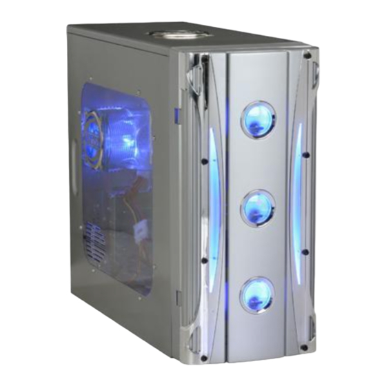
X-Cruiser Series Installation Guide
1:Unscrew the thumb screws
from Side Panel.
4:Put the motherboard stand-offs 5.Sit the motherboard on the
on the motherboard tray.
7.Screw in all the screws into the
motherboard stand-offs
2.Pull the side panel back then
pull out.
motherboard tray.
8.Same as Step 7.
3:Find the motherboard stand-offs
from the enclosed screw box.
6.Find screws in the screw box.
Advertisement
Table of Contents

Related Manuals for Apevia X-Cruiser


Summary of Contents for Apevia X-Cruiser
- Page 1 X-Cruiser Series Installation Guide 1:Unscrew the thumb screws from Side Panel. 4:Put the motherboard stand-offs 5.Sit the motherboard on the on the motherboard tray. 7.Screw in all the screws into the motherboard stand-offs 2.Pull the side panel back then pull out.
- Page 2 9.Take out front panel: (Optional. Only if you need to install front fans or replace LCD) Step (1): Unscrew the side panel panel (motherboard side) Step (4): Unscrew the other 2 screws from the other side. 11.Put the front panel back and screw to secure.
- Page 3 14.Screw all 5.25” drives in place. 17.3.5” Internal Drives: Install 3.5” hidden drivers such as hard drive and zip drive. 20.Plug into your motherboard. Different M/B has different layout. from power supply.(for P4 only) 15.3.5” External Drives: Force out 3.5” metal plate and drive cover with a screw driver.
- Page 4 23.Find 2*USB Cables.(USB1 & USB2) 26.Plug them onto your M/B. Please refer to M/B user manual. 29.Install case speaker onto M/B following M/B user manual. 24.Plug USB cables to your M/B. Please refer to M/B User Manual. 27.Find “Power SW” and “+P LED” 28.Find “Case Speaker” from “-P LED”...
- Page 5 32.LCD Temperature Readout: Connect 4-pin Male connector from LCD to a 4-pin Female connector from power supply. 35.You can either tape the sensor on hard drive or on CPU Heat sink or leave it inside the case to get the overall system temperature. shows temperature readout with 37.Fan Speed Controller: Find a 4pin male connector from front panel with “Input DC 12V”...
- Page 6 40.After connecting the fan speed controller, you would be able to read the fan speed from the front fan speed gauge. 43.Find “Case Feet” in the screw box. Lay case down and put “Case Feet” on. Note: 1.You can link together all the 4-pin connectors(male to female) from all the case fans, LCD, LED, HDD just use one of the 4-pin Molex connectors from power supply.
-
Page 7: Pin Assignment
Description USB Power (+5V) for Port 2 USB Negative Signal for Port 2 USB Positive Signal for Port 2 USB GROUND Front Microphone Input Signal Front Microphone Power MIC-POWER Front Right Channel Audio Signal Front Left Channel Audio Signal PIN ASSIGNMENT DIAGRAM Signal Color...
Need help?
Do you have a question about the X-Cruiser and is the answer not in the manual?
Questions and answers